


SECTION 2
Camera Hardware Interface
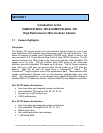
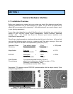
2.1 Installation Overview
Before you integrate your camera into your system you should first determine some basic
operating parameters such as what resolution you need. Do you know the speed of the
object that your camera will be inspecting? One additional point you want to keep in mind
is your lighting requirement.
Some other major items that you should identify early on in developing your system is the
source of your EXSYNC control signal (framegrabber, custom controller, shaft/web
encoder, etc.). You should also know—in advance—your sensor resolution and
magnification requirements.
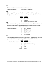
We will use a simple example to reinforce what we just told you in the above. Let’s say that
you have the following system to set up: inspect a web 10cm wide, moving at 2m/s, and
you want 100µm on the web to be represented by one pixel (13µm).
Number of Pixels Total width of image
= 10 cm = 1000 pixels
Necessary Desired resolution 100µm per pixel
Magnification Pixel size
= 13µm = 0.130
Desired resolution 100µm per pixel
EXSYNC Web speed
= 2m/s = 20KHz
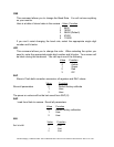
Desired resolution 100µm
Shaft Encoder You require one pulse for every 100µm of
Circumference object travel. Assuming a shaft/web encoder = 0.10m
Producing 1000 pulses/rev., shaft
Circumference must be 1000 x 100µm
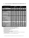
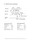
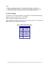
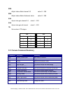
Remember, TDI cameras require PRECISE synchronization with the object velocity! (See
example images below.)
Fairchild Imaging • CAM/CCD 2KCL.TDI & CAM/CCD-4KCL.TDI Line Scan Camera User’s Manual • Rev C• 13 of 30
Bad TDI S
y
nchronization
Good TDI Synchronization