


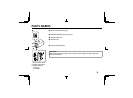
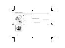
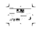
PARTS NAMES
7 Power indicator (POWER)
Comes on when the power to the camera is on.
8 Video output connector (VIDEO OUT: BNC type)
Connect this connector to a device such as a VCR or monitor with a VIDEO IN connector.
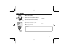
9 Line phase adjustment volume (LINE PHASE)
When using two cameras or more, the image on the monitor may roll vertically when switching sources. This
rolling can be minimized by turning this volume.
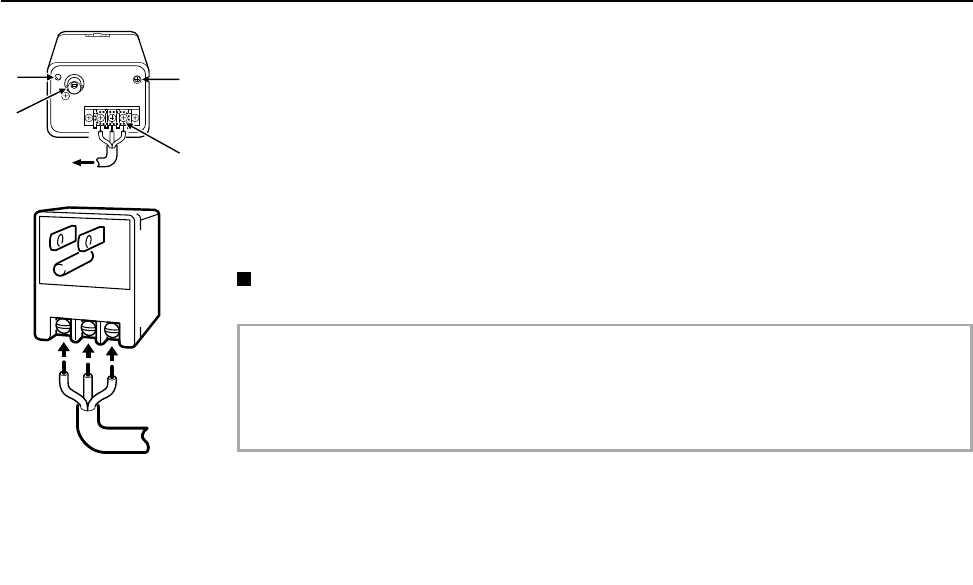
F 24 V AC input terminal (24 V AC, GND)
With this camera use only the 24 V AC power adaptor model No. VPT-115 available from Sanyo.
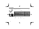
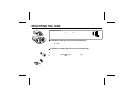
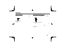
Power supply connections
Use a 3 wire grounded cable (22 AWG or more), and connect as shown by the illustration.
CAUTION:
• To prevent camera and/or AC adaptor failure, pay close attention to polarity when making the
connections.
• To prevent fire hazard any UL listed wire rated VW-1, should be used for the 24 V AC cable input
terminal.
7
9
F
GRD
AC
AC
8
L53S4/US GB 1998, 10, 27
6 English