


INSTALLATION
Note:
When setting up this camera, make sure that it is installed securely. If it
is not installed correctly, it may fall down. In addition, do not touch the
camera in places except where settings and adjustments are necessary.
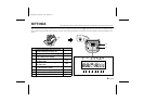
Coaxial cable type and maximum length
•
Cable type RG-59U (3C-2V), 250 m maximum.
•
Cable type RG-6U (5C-2V), 500 m maximum.
•
Cable type RG-11U (7C-2V), 600 m maximum.
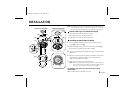
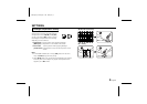
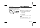
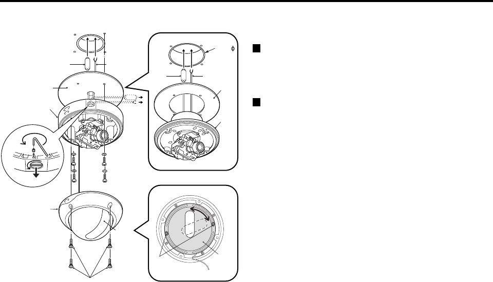
Installing the Model VDC-D1184VA
1
Use the supplied hexagonal wrench to remove the four fixing
screws
(B)
of dome cover
(A)
.
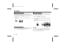
2
Make screw holes and a cable hole in the cushioning sheet
(D)
that attaches to the back of the camera unit
(C)
.
3
Attach the cushioning sheet (double-sided tape) to the back of the
camera unit.
4
Align the camera unit with the surface of the ceiling, make marks
on the ceiling in the places where the screw holes are to be
drilled, and then drill the four holes.
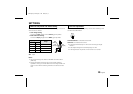
5
Cut a hole in the ceiling for routing the cables.
Note:
When routing the cables in the ceiling, use the accessory hexagonal
wrench (small) to loosen the cable cover fixing screw (E) at the rear
of the unit, and then remove the cable cover screw (F).
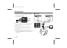
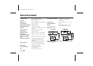
The following step differs only when installing the Model
VDC-D2184VA
Make a cable hole with a diameter of 73 mm.
73mm
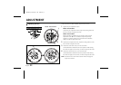
(A)
(B)
(H)
(G)
(K)
(D)
(C)
(Model VDC-D1184VA)
(Model VDC-D2184VA)
(J)
(I)
(H)
(G)
(C)
(D)
(E)
(F)
L5AK4/US, L5AL4/US GB 2003, 6, 6
4
English