15
Installation of bracket
1. Cut out the installation template (enclosed with transducer) along the dotted line.
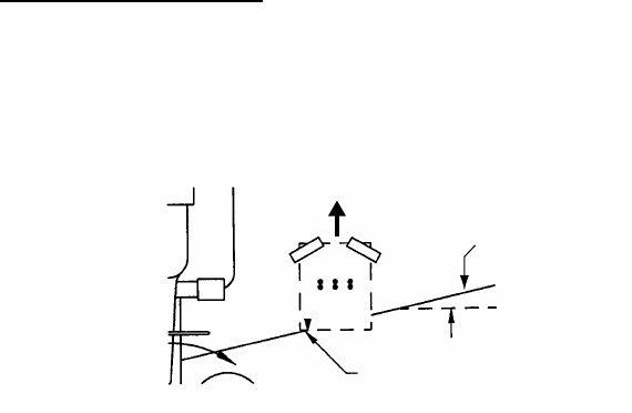
2. At the selected location, position the template, so the arrow at the bottom is
aligned with the bottom edge of the transom. Being sure the template is parallel to
the waterline, tape it in place.
Positioning the template
Warning: Always wear safety goggles and a dust mask.
3. Using a 4 mm, #23, or 9/64" bit, drill three holes 22 mm (7/8") deep at the loca-
tions indicated. To prevent drilling too deeply, wrap masking tape around the bit 22
mm (7/8") from the point.
Fiberglass hull: Minimize surface cracking by chamfering the gelcoat. If a cham-
fer bit or countersink bit is not available, start drilling with a 6mm or 1/4" bit to a
depth of 1 mm (1/16").
4. If you know your transom angle, the bracket is designed for a standard 13
° tran-
som angle.
11
°-18° angle: No shim is required. Skip to step 3 in "Adjusting".
Other angles: The shim is required. Skip to step 2 of "Adjusting".
If you do not know the transom angle, temporarily attach the bracket and sensor to
the transom to determine if the plastic shim is needed.
5. Using the three #10 x 1-1/4" self-tapping screws, temporarily screw the bracket to
the hull. DO NOT tighten the screws completely at this time. Follow the step 1-4 in
"Attaching the sensor to the bracket", before proceeding with "Adjusting".
Align template vertically.
Deadrise ang
Slope of h
parallel to
waterline
Align template arrow with
bottom edge of transom.


