


iv
TABLE OF CONTENTS
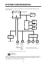
SYSTEM CONFIGURATION ........................................................................................... v
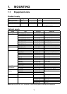
1. MOUNTING ................................................................................................................. 1
1.1 Equipment Lists ..................................................................................................................1
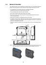
1.2 Network Sounder................................................................................................................2
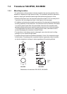
1.3 Transducer 520-5PSD, 520-5MSD.....................................................................................3
1.3.1 Mounting location.......................................................................................................3
1.3.2 Acceptable mounting locations ..................................................................................4
1.3.3 Installation procedure ................................................................................................4
1.4 Transducer 525-5PWD (transom mount) ...........................................................................6
1.4.1 Installation for flat hulls...............................................................................................6
1.4.2 Installation for deep-V hulls........................................................................................7
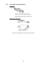
1.4.3 Transducer preparation..............................................................................................7
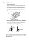
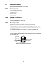
1.5 Inside Hull Mount................................................................................................................8
1.5.1 Necessary tools..........................................................................................................8
1.5.2 Remarks on installation..............................................................................................8
1.5.3 Selecting the mounting location .................................................................................8
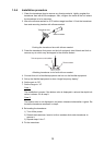
1.5.4 Installation procedure.................................................................................................9
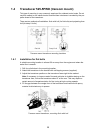
1.6 Optional Water Temperature Sensor ST-02MSB, ST-02PSB ..........................................10
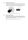
1.7 Optional Temperature Sensors ........................................................................................11
1.7.1 Transom mount temperature sensor T-02MTB........................................................11
1.7.2 Thru-hull temperature sensor T-02MSB, T-03MSB .................................................12
1.8 Optionial Triducers ...........................................................................................................13
1.8.1 Thru-hull triducer 525STID-MSD..............................................................................13
1.8.2 Transom mount triducer 525STID-PWD ..................................................................13
2. WIRING...................................................................................................................... 19
2.1 Optional Temperature/Speed Sensor, Temperature Sensor............................................20
2.2 Wiring Optional 1 kW Transducer.....................................................................................21
3. INITIAL SETTINGS, OPERATION ............................................................................ 22
3.1 Selecting the Transmission Power ...................................................................................22
3.2 MODE SW ........................................................................................................................23
3.3 Operation Check (LED) ....................................................................................................24
4. MAINTENANCE......................................................................................................... 25
4.1 Maintenance .....................................................................................................................25
4.2 Replacing the Fuse...........................................................................................................26
PACKING LIST............................................................................................................ A-1
OUTLINE DRAWINGS ................................................................................................ D-1
INTERCONNECTION DIAGRAM ................................................................................ S-1