26
Operation
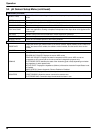
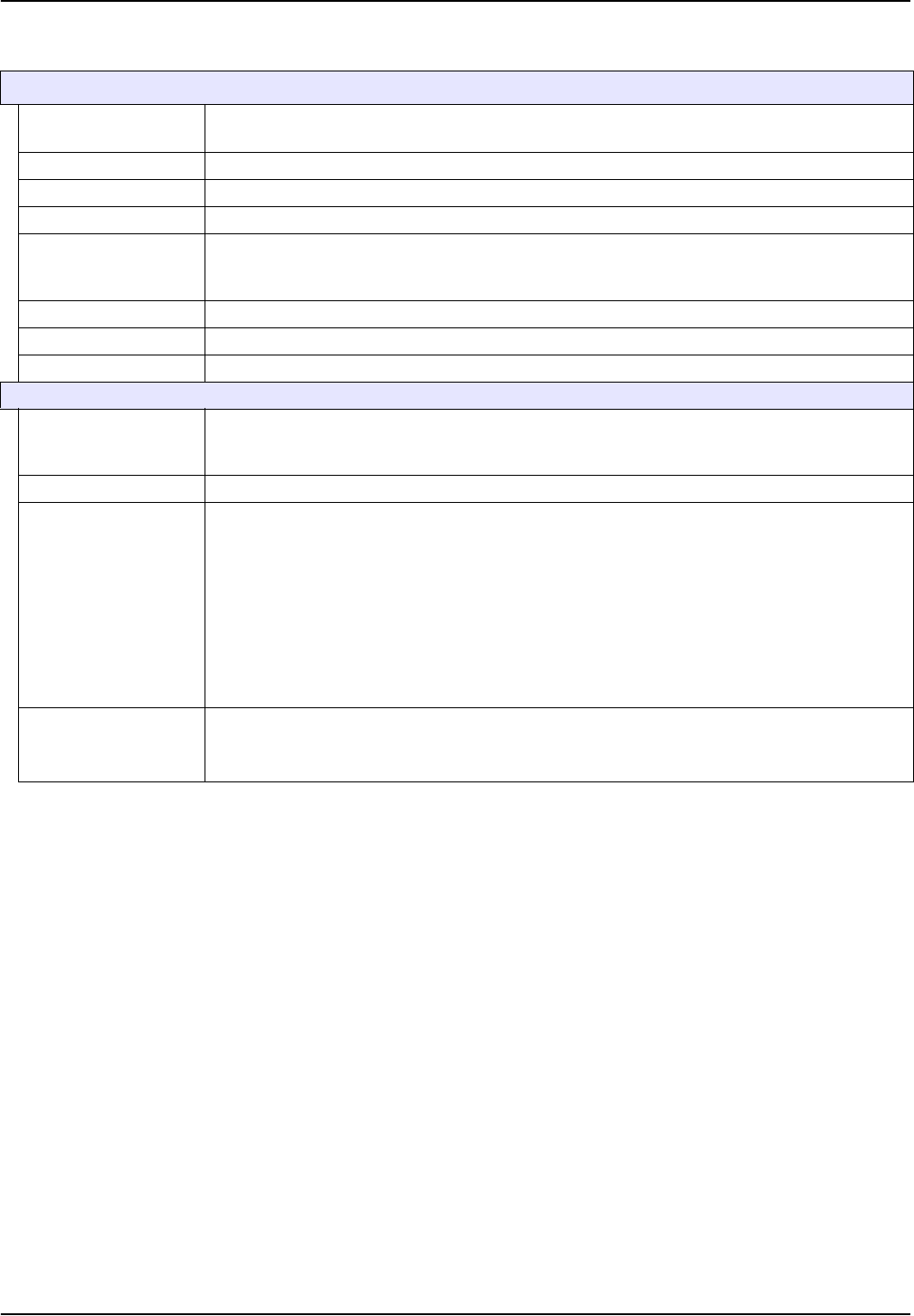
CONFIGURE (continued)
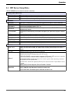
REJECT FREQ
Choose 50 or 60 Hz depending on the power line frequency for optimal noise rejection. Default is
60 Hz.
FILTER Select 0–60 second signal averaging time.
TEMP ELEMENT Select type of temperature element from the displayed choices.
SELECT BUFFER Select the buffer type (standard 4, 7, 10 or DIN 19267) from the displayed choices.
PURE H20 COMP
Allows the user to specify that ammonia, morpholine, or other user-defined electrolyte is being
used in the application, allowing a temperature-dependent linear slope factor to be applied to the
measured pH.
CAL DAYS Number of days since the last calibration. Default notification at 60 days.
SENSOR DAYS Number of days the sensor has been in operation. Default notification at 365 days.
DEFAULT SETUP Resets all user-editable options to their factory-defaults.
DIAG/TEST
PROBE INFO
Display the sensor type, entered name of the sensor (Default: Digital Gateway serial number and
name), the sensor serial number, the software version number, and the sensor driver version
number.
CAL DATA Displays the pH slope and the date of the last calibration.
SIGNALS
SENSOR SIGNAL: Displays the sensor output in mV
SENSOR ADC COUNTS: Displays the sensor ADC counts
TEMP ADC COUNTS: Displays raw data for temperature ADC counts. ADC counts are
comparable to A/D counts and are for sensor electronic diagnostic purposes only.
ELECTRODE STATE: Identifies the state of the electrode (good or bad) depending on whether
the impedance is within preset limits.
ACTIVE ELECT: Displays the impedance (Mohms) of the active electrode if Imped Status is set
to Enabled.
IMPED STATUS: Sensor diagnostic. Choose Enabled or Disabled.
COUNTERS
SENSOR DAYS: Displays the cumulative days the sensor has been in use.
RESET SENSOR: Allows the sensor counter to be reset to zero.
ELECTRODE DAYS: Cumulative days the electrode has been in use.
5.4 pH Sensor Setup Menu (continued)


