


Congratulations on your purchase of an Ikelite Digital Camera
Housing. Ikelite has over 45 years of experience in the underwater
photographic and lighting market. Our products are designed and
built in the USA by Ikelite for both the professional and amateur
photographer.
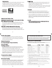
The clear housing permits instant visual inspection of the camera
and all sealing surfaces as well as complete monitoring of controls
and camera LCD screens.
Ikelite Digital Housings are slightly negative in salt water for
stability. This housing has been water pressure tested at the
factory. Housing is pressure tested to 200’ (60m).
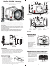
Ikelite SLR-DC Housing
i n s t r u c t i o n m a n u a l
#6851.3 for Olympus E-3
I
K
E
L
I
T
E
2
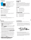
AEL/AFL
Strobe
Mount
R
ubber
Handle
Q
uick-Release
Strobe
M
ount
Gear Sleeve
Drive Gear
Z
oom
Control
Lid
Snap
L
ens
R
elease
Preview
Button
Lid
Snap
Shutter
R
elease
Port Lock
A
luminum Tray
Port
O
pening
IKELITE
L
id
Snap
Sub-dial
A
EL/
A
FL
Quick
R
elease
Button
E
xternal Strobe Connector
a
nd Waterproof Cap
V
iewfinder Port
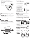
[E] TTL Circuit Buttons
[
F] LiveView
[G] White Balance
[H] Playback
[ I ] Arrow Pad
[J] Image Stabilization
[K] Card Cover Lock
[
L] AF Button
A
B
C
D
L
ens
R
elease
Zoom
[
A] Erase
[B] Info
[
C] Menu
[D] LiveView
S
hutter
R
elease
E
F
G
H
I
J
Main Dial
P
ower Switch
K
L
M
N
N
N
O
P
Q
[M] Mode
[N] Flash
[
O] White Balance
[
P] +/-
[Q] ISO
FRONT VIEW
BACK VIEW
3
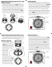
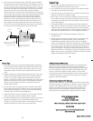
Camera
Tray
Camera
Mounting
Bolt
Gear
Sleeve
Port
O'ring
Optional
Port
Lid
Snap
Back O’ring
Sub-dial
AEL/AFL
Shutter
Release
Preview Button
OOppeenniinngg tthhee HHoouussiinngg
1. Lid Snaps have a
LLoocckk
.
To open, push Lid Snap Lock
forward and lift as shown. Keep
pressure on the Lid Snap so it
does not fly open quickly.
Some lid snaps have a lot of
spring tension once they go over center, have a firm grip on the
lid snap. Lid Snaps may be opened one at a time.
Lift
Push Forward
Lid Snap Lock
CCaammeerraa SSeettuupp
1. In the E-3 custom menu settings, select “button/Dial”, then
select “button Timer”, scroll to “Hold” and press “OK”. This will
allow each camera function to remain on the LCD screen for
adjustment after a push button is pressed and released.
2. REMOVE eye-cup from camera.
IInnssttaalllliinngg tthhee CCaammeerraa
Remove the back from
the housing. The
mounting tray for the
camera is secured to
the housing back.
Position the camera
with lens on the tray
and secure it with the
mounting bolt which
threads into the
camera’s tripod socket.
Use a flathead
screwdriver
(recommended) or coin
to tighten the
mounting bolt so the camera bottom is flush against the tray.
O‘ring
Mounting Bolt
Camera Tray
O
LYMPUS
4
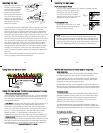
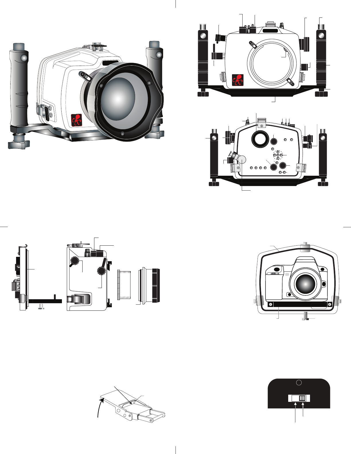
SSeettttiinngg tthhee CCoonnvveerrssiioonn CCiirrccuuiittrryy SSttrroobbee IIDD SSwwiittcchh..
Inside the housing back on the black panel housing (see
illustration next page) the conversion circuitry is a switch for
setting the DS Substrobe ID.
Set the switch to the Model
of DS Substrobe being used,
SD125/DS200 or DS51.
• When using dual strobes
of different models such as
a DS51 and a DS125, set the
ID switch to DS51.
DS DS
125 50/51
200 80
++
DS125 / DS200
DS50 / DS51 / DS80
SIDE VIEW