


13
I
I
n
n
s
s
t
t
a
a
l
l
l
l
i
i
n
n
g
g
t
t
h
h
e
e
P
P
o
o
r
r
t
t
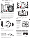
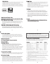
There are two port locks on
the front of the housing.
(See housing front) Each
p
ort lock has a Release
Button, lift the release
button and slide each Port
Lock away from the port
opening. In the unlocked
position the Release Button
will remain in the up
position as shown.
T
o prepare the port for installation, remove the port o’ring and
lightly lubricate it. The port seal is a side-to-side seal and
requires the o’ring to be lightly lubricated for easy installation.
Put a small amount of lubricant on your fingers and draw the
o
’ring through your fingers to lightly lubricate it. Do not stretch
the o’ring. Check that the lip of the port where the o’ring fits
and the sealing surface on the housing are clean. Place the port,
with o’ring into the housing’s port opening. Press down on the
port firmly and evenly until you feel the port slide into place.
Continue to push down on the port and push each port lock
forward until it clicks into place. It may help to slightly rotate
the port as you push in on the port lock. When the port lock
clicks into place the Release Button will drop down against the
port lock.
Check around the perimeter of the port seal to see that the
o’ring is properly sealed and not extruded.
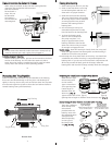
Port Lock
Release
Button
L
ift Release
B
utton to
U
nlock
P
ull Back to
D
isengage
P
ort
U
nlocked Position
Locked Position
I
I
n
n
s
s
t
t
a
a
l
l
l
l
i
i
n
n
g
g
t
t
h
h
e
e
P
P
o
o
r
r
t
t
c
c
o
o
n
n
t
t
.
.
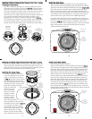
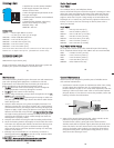
PPoorrtt SSeeaall IInnssiiddee VViieeww
If the port is installed before the camera is inserted into the
housing, look on the inside of the
housings at the port seal. Check
to see that the o’ring is properly
sealed as shown in figure 1 and not
extruded as shown in figure 2.
TToo RReemmoovvee PPoorrtt
To remove the port lift up on each
Release Button and slide the port
lock away from the port.
Fig. 1
Fig. 2
14
C
C
a
a
u
u
t
t
i
i
o
o
n
n
:
:
After installing the port, turn the Zoom Control knob on the
housing. If the Zoom Control is difficult to turn, the gear sleeve
may be warped. If so reduce or omit any rubber installed on the
Zoom Clamp. (Fig.H on pg.11).
If the Zoom Clamp is still warped,
use of the #5509.28 package may be required. (See page 8)
15
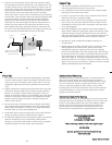
UUssiinngg tthhee CCoonnvveerrssiioonn CCiirrccuuiittrryy
((SSeett DDSS SSuubbssttrroobbee ttoo TTTTLL mmooddee))
•• MMooddee aanndd CCoommppeennssaattiioonn BBuuttttoonnss
The Conversion Circuitry default is set to TTL. To switch between
TTL and Manual Modes depress both Mode Buttons at the same
time and keep them depressed until you see the desired Yellow
LED Mode illuminate.
•• TTTTLL MMooddee
(indicated when the Yellow LED directly below TTL is
illuminated). TTL Mode is the default setting. When the DS
Substrobe is powered ON the Yellow TTL LED will illuminate.
None of the Red LEDs will illuminate. This indicates that NO (+)
plus or (-) minus compensation is selected. Depress the Mode
buttons to select +/- compensation. Note that the TTL +/-
compensation values are in the yellow bar with the heading TTL.
•• MMaannuuaall MMooddee
(indicated when the Yellow LED directly below
the M is illuminated). When the Manual Mode is selected the Red
LED directly below the F (full power) will illuminate. Note that
the Manual minus (-) compensation values are in the black bar
with the heading M.
((SSeett DDSS SSuubbssttrroobbee ttoo TTTTLL mmooddee))
3 3
UUssiinngg EExxtteerrnnaall SSttrroobbeess CCoonntt..
16
NNOOTTEE:: DDSS SSuubbssttrroobbee UUpp--ddaattee mmaayy bbee rreeqquuiirreedd..
DDSS5500 SSuubbssttrroobbeess
• DS50 SubStrobes with a Serial Number below 63,850 can not
be updated to operate with the TTL Conversion Circuitry.
• DS50 SubStrobes with a Serial Number between 63,850 and
69,999 operate with the TTL Conversion Circuitry, but require
update to provide optimum performance.
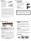
• DS50 Substrobe with a Serial Number of 70,000 or higher or
with one of the two following labels in the battery compartment
provide optimum performance with the TTL Conversion Circuitry.
DDSS112255 SSuubbssttrroobbeess
• DS125 Substrobes with a Serial Number below 2,500 must be
updated to operate correctly with the TTL Conversion Circuitry.
• DS125 Substrobes with a Serial Number between 2,501 and
4,900 operate with the TTL Conversion Circuitry but require
update to provide optimum performance.
• DS125 Substrobe with a Serial Number of 5,000 or higher or
with one of the two following labels in the battery compartment
provide optimum performance with the TTL Conversion Circuitry.
ikelite
SubstrobeSubstrobe
MOD-NC
serial number
serial number
FFoorr SSuubbssttrroobbee UUpp--DDaattee::
Contact Ikelite for information.