


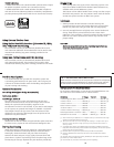

IInnssttaalllliinngg tthhee ZZoooomm CCllaammpp && GGeeaarr SSlleeeevvee OOnn TTyyppee 22 LLeennsseess
Due to the larger diameter of lens opening on Type 2 lenses, the
Zoom Clamp and Gear Sleeve need to be installed from the rear
(bayonet end) of the lens. Use the housings Lens Release Control
and remove the camera lens from the camera body.
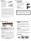
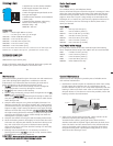
IInnssttaalllliinngg tthhee ZZoooomm CCllaammpp
The Zoom Clamp has springs so
it can be expanded to fit over the
Zoom ring of the lens as shown
in
((FFiigg.. II))
. Install the Zoom Clamp
with the extension tabs toward
the rear element of the lens. After
installing the Zoom Clamp, check
that when rotating the Zoom
Clamp it rotates the
Zoom ring on the
lens. If the Zoom
Clamp is not tight
enough to rotate
the Zoom ring on
the lens, remove
the Zoom Clamp
and install the rubber
strips (supplied) to the inside of
the Zoom Clamp as shown
((FFiigg.. HH))
.
Two thickness of rubber strips
are provided. Start by installing
the thinnest rubber strips, if the
Zoom Clamp still is not tight
enough use the thicker rubber
strips. Reinstall the Zoom Clamp.
11
clamp
Type 2 Installation: Figure 1
TOP OF HOUSING
Figure I
Type 2
lens
apply
rubber strips
to inside of
clamp
Figure H
zoom
ring
align
zoom clamp
extension
grooved
tab with
gear sleeve
ribs
10
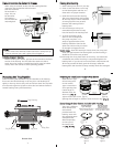
IInnssttaallll tthhee GGeeaarr SSlleeeevvee
After the Zoom Clamp is installed, lower the appropriate Gear
Sleeve over the Zoom Clamp aligning the Gear Sleeve ribs with the
grooves in the Zoom Clamps extended tabs as shown
((FFiigg..DD && EE))
.
Note that the ribs of the Gear Sleeve should slide freely in the
grooves of the Zoom Clamp. If the Gear Sleeve does not slide
freely, remove any rubber strips on the inside of the Zoom Clamp,
if no rubber strips are installed then try using the Zoom Clamp
and Gear Sleeve for Type 2 lenses in the #5509.28 package.
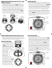
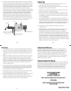
Lower the Gear Sleeve into the port opening of the housing so
the teeth on the Gear Sleeve mesh with the teeth on the housing
D
rive Gear
((FFiigg.. GG))..
W
hen the port is installed it will lock the
Gear Sleeve in place. After installing the port, rotate the housings
Zoom Control Knob to see that the Gear Sleeve is properly
rotating the lenses Zoom ring.
IKELITE
Figure G
b
lack housing
s
leeve/
d
rive gear
m
esh
gear sleeve
w
ith
black housing
d
rive gear
9
IInnssttaalllliinngg tthhee ZZoooomm CCllaammpp && GGeeaarr SSlleeeevvee OOnn tthhee TTyyppee 11 LLeennsseess
IInnssttaalllliinngg tthhee ZZoooomm CCllaammpp
The Zoom Clamp has springs so it can be expanded to fit over
the Zoom ring of the lens as shown in
((FFiigg.. CC))
. Install the Zoom
Clamp with the extension tabs toward the rear element of the
l
ens. After installing the Zoom Clamp, check that when rotating
the Zoom Clamp it rotates the Zoom ring on the lens. If the
Zoom Clamp is not tight enough to rotate the Zoom ring on the
lens, remove the Zoom Clamp and install the rubber strips
(
supplied) to the inside of the Zoom Clamp as shown
((FFiigg.. FF))
.
Two thicknesses of rubber strips are provided. Start by installing
the thinnest rubber strips, if the Zoom Clamp still is not tight
enough use the thicker rubber strips. Reinstall the Zoom Clamp.
T
ype 1 Installation: Figure A
Figure A
Type 1 Installation: Figure B
Figure B
T
ype 1 Installation: Figure C
F
igure C
Figure C Figure D Figure E
Type 1 lens
mounted
to camera
gear sleeve
r
ibs
a
lign with
groove in
z
oom clamp
extension
t
ab
mesh
g
ear sleeve ribs
with black housing
d
rive gear
z
oom
ring
apply
r
ubber strips
to inside of
c
lamp
Figure F
12
IInnssttaalllliinngg tthhee GGeeaarr SSlleeeevvee
After the Zoom Clamp is installed.
Place the Gear Sleeve in the port opening of the housing
((FFiigg.. II))
.
Lower the lens through the Gear Sleeve, aligning the grooves in
the Zoom Clamp with the ribs on the Gear Sleeve. Note that the
ribs of the Gear Sleeve should slide freely in the grooves of the
Zoom Clamp. If the Gear Sleeve does not slide freely, remove any
rubber strips on the inside of the Zoom Clamp
((FFiigg.. HH))
or use
thinner rubber strips. Reinstall the Zoom Clamp on the lens and
lower the lens through the Gear Sleeve, aligning the grooves in
the Zoom Clamp with the ribs on the Gear Sleeve. Remount the
lens to the camera body, make sure the lens is locked into the
camera body. Position the Gear Sleeve teeth so they mesh with
the housing drive gear
((FFiigg.. JJ))
. When the port is installed it will
lock the Gear Sleeve in place. After installing the port, rotate the
housing Zoom Control Knob to see that the Gear Sleeve is properly
rotating the lenses Zoom ring.
Figure J
black housing
sleeve/
drive gear
mesh
gear sleeve
with
black housing
drive gear
IKELITE