


5
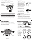
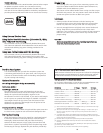
When using an external strobe, slide the housing hotshoe
connector into the hotshoe camera mount
S
lide the connector
forward until it
stops. This can
be done after
t
he camera is
secured with the
mounting bolt.
External Strobe Connector
W
aterproof Cap
O'ring
Housing Back
Hotshoe
C
C
a
a
u
u
t
t
i
i
o
o
n
n
:
:
Do not remove the External Strobe Connector’s waterproof cap
unless an external sync cord is going to be plugged in.
I
I
n
n
s
s
t
t
a
a
l
l
l
l
i
i
n
n
g
g
C
C
a
a
m
m
e
e
r
r
a
a
i
i
n
n
H
H
o
o
u
u
s
s
i
i
n
n
g
g
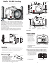
Before installing the camera, pull out on the controls in the front
section of the housing. This will allow the camera to slide in
easier. Once the camera is installed and the lid snaps have been
closed, return the controls to their operating position.
F
F
l
l
a
a
s
s
h
h
C
C
o
o
n
n
n
n
e
e
c
c
t
t
i
i
o
o
n
n
f
f
o
o
r
r
E
E
x
x
t
t
e
e
r
r
n
n
a
a
l
l
S
S
t
t
r
r
o
o
b
b
e
e
s
s
6
C
C
l
l
o
o
s
s
i
i
n
n
g
g
t
t
h
h
e
e
H
H
o
o
u
u
s
s
i
i
n
n
g
g
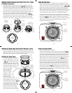
1. Place housing face down in your lap.
2. Check to see that there is an o’ring
on the housing back and that it is
clean and in its proper location.
3. Guide the back onto the housing.
The o’ring should touch the housing
all the way around. There should be
an even gap all the way around
between the housing and the
housing back.
4
. Lift the lid snaps so they are
extended and place the lid snap
into the hook on the housing back.
5. To close the housing push
down on the lid snaps until
they snap into place . Lid
snaps on opposite sides of the
housing should be closed at the
same time. Be sure they are down
far enough to engage the lock.
DDoouubbllee cchheecckk
- Once the housing is closed, check the o’ring seal.
Check the gap between the housing back and the housing, it
should be even all the way around.
Look through the clear plastic back at the o’ring. You should see
a darkened area where the o’ring is compressed against the
housing back. If you do not see an even black compression seal
all the way around the back, open the lid snaps, reseat the
housing back and close the lid snaps. Visually check the seal again.
7
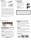
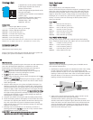
MMoouunnttiinngg tthhee TTrraayy//HHaannddlleess
When mounting the aluminum tray and handles to the housing,
first insert the black bushings in the tray slots. The bushings fit
tightly in the tray slots so they will not fall out when the tray bolts
are removed. Tighten tray bolts so that slots are farthest forward
toward housing front (see illustration).
Bottom of
Aluminum Tray
Bottom View
Tray Slot
Tray Bolt
Tray Bushing
Tray Bushing
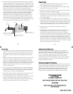
Normally used with
Type 1 lens (Fig.1)
#9059.8 small diameter clamp:
For use with #0073 sleeve
+
#0073 sleeve: Use with
small diameter zoom clamp
#9059.8
Figure A
PPrreeppaarriinngg ttoo IInnssttaallll ZZoooomm CCllaammpp && GGeeaarr SSlleeeevvee
Determine the type
of lens being used
on the camera.
Type 1 Lenses have
a lens opening that
is NOT larger in
diameter than the
zoom ring.
((FFiigg.. 11))
.
Type 2 Lenses have a lens
opening that IS larger in diameter than the zoom ring.
((FFiigg.. 22))
.
ZZoooomm CCllaammppss && GGeeaarr SSlleeeevveess IInncclluuddeedd wwiitthh HHoouussiinngg
There are 2 different
Zoom Clamps and
Gear Sleeves
provided with the
housing. Start with
the suggested Zoom
Clamp and Gear
Sleeve depending
on the Type of
lens being used.
See
((FFiigg.. AA oorr BB))
thick ribs
wide
grooved
extension
tabs
8
Figure B-Type 2 Lens
Figure A-Type 1 Lens
lens
opening
zoom
ring
bayonet
mount
Type 1 lens Type 2 lens
(Figure 1) (Figure 2)
Figure G
Normally used with
Type 2 lens (Fig.2)
#5509.28 Package
#9059.9 large diameter clamp:
For use with #0073.1 sleeve
+
#0073.1 sleeve: Use with
large diameter zoom clamp
#9059.9
Figure B
thin ribs
narrow
grooved
extension
tabs
Figure F