


Security Software—Software Overview
Intel
®
EP80579 Software for Security Applications on Intel
®
QuickAssist Technology
PG August 2009
14 Order Number: 320183-004US
3.0 Software Overview
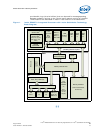
This chapter presents the high-level architecture of the Software for Intel
®
EP80579
Integrated Processor product line, using concepts from the "4+1 view model" of
software architecture, as described in [4+1]. These views are interpreted as follows:
• Section 3.3, “Logical View” on page 15 describes the collection of software
components in terms of their key responsibilities, interfaces, and dependencies.
• Section 3.4, “Development View” on page 17 describes the static organization of
the software in its development environment (that is, folders and files).
• Section 3.5, “Process View” on page 18 captures concurrency and synchronization
aspects of the architecture. This includes the mapping of software onto hardware,
reflecting the distributed aspect of the architecture; this is sometimes considered
part of the Physical or Deployment View.
• Section 3.6, “Deployment View” on page 18 describes the mapping of the software
into kernel modules.
• The architecture is illustrated with a few selected use cases or scenarios which
become a fifth view, the Scenario View. In this document, the Scenario View is
described in Part 2, “Using the API” on page 41.
Before looking at these views, however, other concepts relevant to the architecture are
introduced:
• Section 3.2, “Shared Memory Allocation” on page 14 describes the concepts of
coherent and non-coherent DRAM.
3.1 What’s New in this Chapter
• Section 3.3.5: New Note explaining cryptographic framework “shim” support.
3.2 Shared Memory Allocation
Two regions of memory exist outside of the normal operating system DRAM, to
facilitate communications between the IA core and the EP80579 with QuickAssist
hardware. These are referred to as the coherent and non-coherent shared memory
regions.
These shared memory regions will be allocated from the available system memory,
starting at the address specified by the Top Of Low Memory (TOLM) register of the
Memory Controller Hub (MCH) downwards. The pre-boot firmware (BIOS) informs the
operating system of the location of the regions, and also configures the hardware to
properly decode the non-coherent memory space by writing the MENCBASE and
MENCLIMIT registers.
The base addresses for each of these regions will be determined by the firmware based
on available memory. Two EFI NVRAM (non-volatile RAM) variables are available for the
user to request a specific amount of space for each of these shared memory regions.
The firmware will make a best effort to accommodate the user’s request, but in the