


- 9 -
CV-M530/531
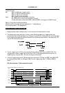
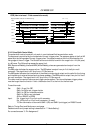
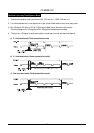
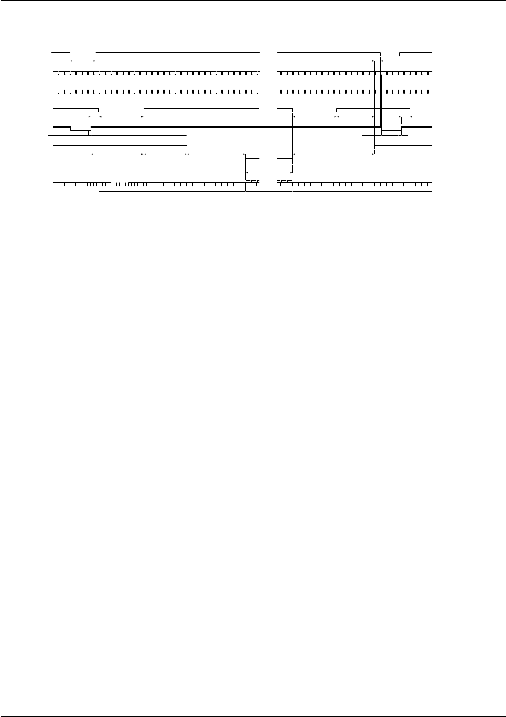
CCIR (Non-interlaced / Field accumulation mode)
Edge pre-select mode
(
for non-interlace only
)
CCIR : 1H = 64µs
TRIG
INT VD
EEN
WEN
EXT HD
INT HD
Effective videoBlanking Blanking
Video out
CCD out
No.10 to 251
Effective pixels
1H more
1.5H 7.5H
7.5H
9H 10H 14H
0.5H
7.5H1.5H6.5H
7.5H
TRIG in1H
25H 287H 25H
Exposure time Exposure time
0.5H
16.5H
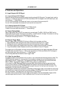
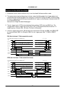
6.3.2. Pulse Width Control Mode
The pulse width control mode will only work in non-interlaced field accumulation mode.
The exposure is controlled by the low period of the ext. trigger pulse. The exposure starts at the first HD
pulse after the falling edge of the ext. trigger pulse. The exposure ends at the first HD pulse after the
rising edge of the ext. trigger. The Shutter can be controlled to be within the range from >1H (> 64 µsec.)
to <60 msec. The AC coupling causes the upper limit.
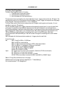
EEN (Exposure ENable) pulse and WEN (Write ENable) pulses are generated and output from the
camera.
The EEN pulse indicates the exposure time. The EEN pulse is output from pin 2 of the 6-pin multi
connector. The signal level is 4.0 Vp-p from a 75 Ohm source.
The WEN pulse indicates the time period of the effective video signal output and is useful for the timing
and interfacing of external devices such as frame grabbers. The WEN pulse is output from pin 6 of the 6-
pin multi connector. The signal level is 4.0 Vp-p from a 75 Ohm source
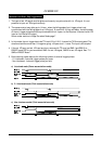
The video must be read out before a new trigger can be applied. The interval between trigger pulses
must be longer than the time for 1 field + the shutter time. It is the limit for the field rate.
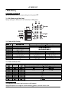
To use this mode
Set: SW1-1, 2 and 3 to OFF
SW1-4 to ON for ext. trigger shutter
SW1-5 to OFF for field accumulation
SW1-6 to ON for non-interlaced
JP12 on PK8057 to OPEN
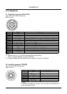
Input: Ext. trigger to pin 5 on 6-pin multi connector.
Ext. HD to pin 6 on 12-pin multi connector. (If used).
75 Ohm termination is done with SW2-1 (HD) and SW2-2 (ext.trigger) on PK8057 board.
Refer to Timing Chart and Cautions on next page.
Detailed switch and jumper setting is described in “7. Mode Setting”.
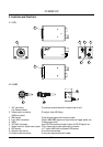
For connections see “5. Pin Assignment”.