


- 13 -
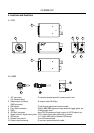
CV-M530/531
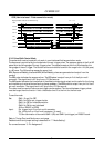
6.3.4. Long Time Exposure Mode
The Long time exposure will work in 3 modes:
1. Interlaced with field accumulation.
2. Interlaced with frame accumulation.
3. Non-interlaced with field accumulation.
The exposure time is the interval between 2 ext. VD pulses sent to the camera VD input. Each ext. VD
pulse will reset and restart the internal VD in the camera as for ext. HD/VD input. So the camera is
synchronized to the external HD/VD supply after each VD input.
An exposure starts after input of an external VD pulse, and ends after the next input of ext. VD, which
again starts a new exposure.
The long time exposure is a continuous process where each external VD will synchronize the camera,
stop an exposure, start a new exposure and read out the previous accumulated signal as interlaced or
non-interlaced fields.
The exposure control can be done by feeding every N
th
VD pulse from the external HD/VD supply to the
camera. N is the wanted exposure time in number of fields. This is typically done in the frame grabber
PC.
The range for long time exposure is from 1 V (a single field) to ∞. However the dark current signal will
increase by longer time, so >2 seconds are not recommended at normal ambient temperature.
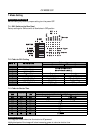
To use this mode:
Set: SW1-1, 2 and 3 to OFF
SW1-4 to OFF for normal shutter.
SW1-5 to ON for frame accumulation or OFF for field accumulation.
SW1-6 to OFF for 2:1 interlaced or ON for non-interlaced.
Jumper JP6 on PK8057 to CLOSE
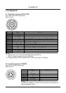
Input: Ext. VD pulses with the exposure interval to pin 7 on 12 pin multi connector.
Ext. HD to pin 6 on 12 pin multi connector.
75 Ohm termination is done with SW2-1 and SW2-2 on PK8057 board.
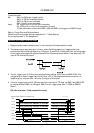
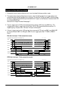
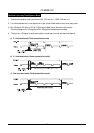
The timing for the external VD interval has to be as follow. (V is the time for a single field)
Interlaced with field accumulation. 1 V or more
Interlaced with frame accumulation. 2 V or integral number of 2V
Non-interlaced with field accumulation. 2 V or more
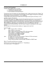
Note:The external HD/VD sync. generator, which supply the ext. VD an HD signals should follow the
scanning standard for the camera setting.
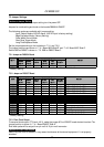
EIA CCIR
Interlaced and field accumulation. 1 V = 262.5 H 1 V = 312.5 H
Interlaced and frame accumulation. 2 V = 525.0 H 2 V = 625.0 H
Non-interlaced and field accumulation. 2 V = 524.0 H 2 V = 624.0 H
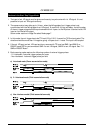
Refer to Timing Chart and Cautions on next page.
Detailed switch and jumper setting is described in “7. Mode Setting”.
For connections see 5. “Pin Assignment”.