


- 10 -
CV-M530/531
Cautions in the Pulse Width Control Mode.
1. Pulse width control mode is effective only in non-interlaced field accumulation mode.
2. The exposure start may be delayed up to 1H max., when the falling edge of ext. trigger pulse is not
synchronized with the falling edge of ext. HD signal. To avoid this 1H jitter and delay, the falling edge
of the ext. trigger pulse should be synchronized within 4.4 µsec. to the HD pulse. It can be the ext. HD
in or the Internal HD out.
See cautions in Edge Pre-select Mode page 7.
3. The ext. trigger input is 75 Ohm terminated as factory setting. (R127 short and SW2-2 on). The
voltage level of the ext. trigger has to be 4.0 Vp-p ± 2.0 V. The duration should be more than 1 H
negative going. >64 µsec. and < 60 msec. The input is AC coupled.
4. If the ext. trigger input and ext. HD input are from a source with TTL level, set SW2-1 and SW2-2 OFF
for non-terminated. SW2-1 for HD signal, SW2-2 for ext. trigger pulse. See “7.2 SW2 on PK8057
Board”.
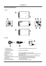
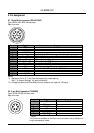
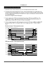
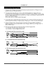
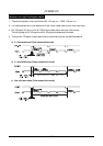
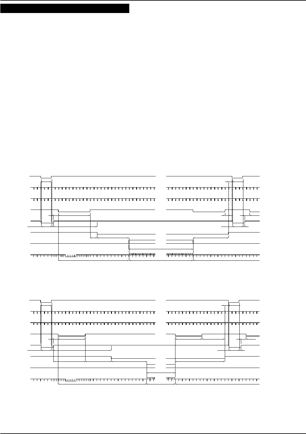
EIA (Non-interlaced / Field accumulation mode)
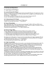
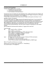
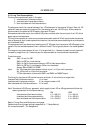
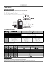
CCIR (Non-interlaced / Field accumulation mode)
TRIG
INT VD
EEN
WEN
EXT HD
INT HD
Effective videoBlanking Blanking
Video out
CCD out
No.10 to 251
Effective pixels
Pulse width control mode
(
for non-interlace only
)
EIA : 1H = 63.5µs
1H more
1.5H 9H
2H 9H 10H
0.5H
9H1.5H1H
TRIG in1H
20H 242H 20H
Exposure time Exposure time
0.5H
12.5H
CCIR : 1H = 64µs
Pulse width control mode
(
for non-interlace only
)
TRIG
INT VD
EEN
WEN
EXT HD
INT HD
Effective videoBlanking Blanking
Video out
CCD out
No.10 to 251
Effective pixels
1H more
1.5H 7.5H
7.5H
9H 10H 14H
0.5H
7.5H1.5H6.5H
7.5H
TRIG in1H
25H 287H 25H
Exposure time Exposure time
0.5H
16.5H