


CV-M40
5
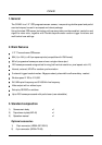
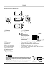
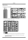
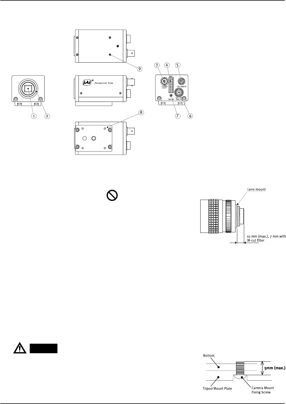
4. Locations and functions
1. CCD sensor
2. Lens mount
3. BNC connector
4. SW1 switch
5. 6 pin multi connector
6. 12 pin multi connector
7. Gain potentiometer
8. Tripod mount plate
9. Screw holes for
Tripod mount plate
:
:
:
:
:
:
:
1/2 “ IT CCD sensor
C-mount type
Video output (VS 1.0 Vpp at 75 Ohm)
Shutter speed and function modes selection
RS 232 input and output / ext. trig input
+12V DC power / video output / sync. input and output
Gain level adjustment
Note :
Rear protrusion on C-
mount lens must be less
than 10 mm (0.4 inch
approx).
When IR-cut filter is used, it
must be less than 7.0 mm
(0.28 inch approx).
When you mount the camera on your system, please make sure to use screws
which have the length less than 5 mm from the camera bottom plate, as it may
cause a serious damage to the PCB inside the camera when the length is
more than 5 mm.
Please be advised that the supplied 4 screws for Tripod mount plate are to be
used exclusively for MP-40, but not for any other mounting adaptor.
CAUTION