


CV-M30
5. Pin Assignment
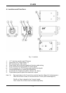
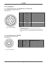
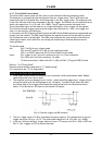
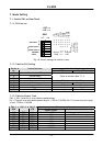
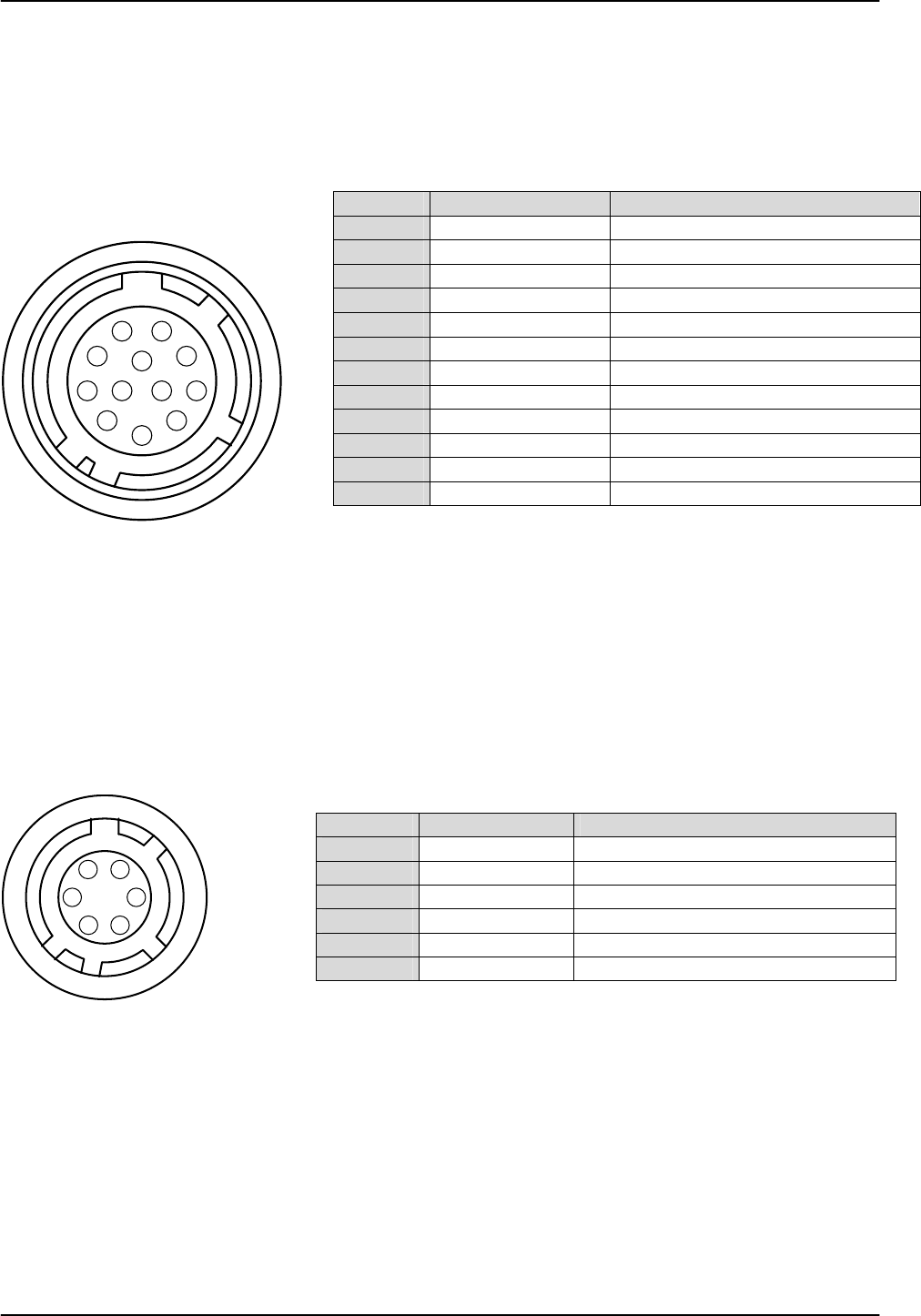
5.1. 12-pin Multi-connector (DC-IN/VIDEO OUT, EXT.HD/VD IN)
Type: HR10A-10R-12PB-01 (Hirose) male
Seen from rear.
Fig. 2. 12 pin connector
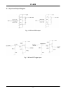
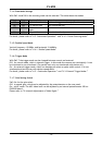
5.2. 6-pin Multi-connector (TRIGGER)
Type: HR10A-7R-6PB (Hirose) male
Pin no Signal Remarks
1 GND
2 +12 V DC input
3 GND
4 Video output
Parallel with the BNC connector. *1)
5 GND
6 HD input
7 VD/trig input
Parallel with pin 5 on 6 pin con. *2)
8 GND
9 EEN output
Parallel with pin 2 on 6 pin con.
10 GND
11 +12 V DC input
12 GND
Notes:
*1) The video signal on pin 4 is in parallel with the BNC connector.
Avoid double termination
*2) If external trigger pulse is input on either No.7 of 12 pin connector or
No. 5 of 6 pin connector, no external VD signal should be input on the
other.
Pin no. Signal Remarks
1
RM1
Normal/Double speed. (SW1-5)
2
EEN Output
Parallel with pin 9 on 12 pin con.
3
GND
4
NC
5
VD/trig input
Parallel with pin 7 on 12 pin con. *2)
6
WEN output
3
4
5
6
7
8
9
10
11
12
1
2
Seen from rear.
1
2
3
4
5
6
Fig. 3. 6 pin connector
- 4 -