


CV-M30
6. Functions and Operations
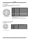
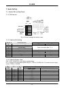
6.1. Input of External HD/VD Signals
As factory setting the camera can be synchronized by external HD/VD signals. The external
supplied HD/VD signal should follow the same standard as the camera setting for speed, scanning
and interlace. The signal level must be 4.0 Vp-p ±2.0V with 75 Ohm termination on. The
termination can be switched off with the internal switch SW1 on the PK8212 board.
The VD input terminal is used for external trigger signal input in the random trigger modes.
If no external HD is connected, the camera will switch to the internal HD.
If no external VD is connected, the camera will continue with its internal VD.
For settings, see “7. Mode Setting.”
6.2. Continuous Operation
For applications that not require asynchronous trigger, but run in continuous mode, this mode is
used. SW1-7 Trigger is set to Normal (OFF). The camera can operate in normal or double speed.
It is set by with Sw1-5 or at pin 1 on 6 pin connector. The exposure time is selected with SW1-1
to SW1-3. The read out can be 2:1 interlaced, non-interlaced or partial scan. It can be set by
SW1-4 and SW1-6. Partial scanning can only operate in non-interlaced mode. Maximum field rate
with partial scan and double speed is 360 fields per second.
To use this mode
Set: SW1-7 to OFF for normal shutter
SW1-4 to and SW1-6 to interlaced, non interlaced.1/2 partial or 1/3 partial
SW1-1, SW1-2 and SW1-3 to shutter speed.
Input: If external synchronizing is used, input HD and VD.
Ext. VD to pin 5 on 6 pin connector or pin 7 on 12 pin connector..
Ext. HD to pin 6 on12-pin connector.
75 Ohm termination is done with SW1-1 (HD) and SW1-2 (VD) on PK8212 board.
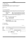
Refer to “6.5.Timing Chart”
For settings, see “7. Mode Setting.”
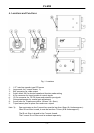
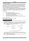
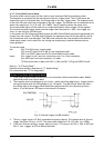
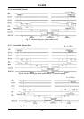
6.3. External Trigger Mode
This camera has two external trigger modes.
1. Edge Pre-select Mode. (Asynchronous reset and exposure start by an external trigger.)
2. Pulse Width Control Mode. (Asynchronous reset and exposure controlled by the low
period of the external trigger.)
Trigger
Trigger
Exposure
Exposure
shutter time
EDGE
PRE-SELECT
PULSE
WIDTH
Readout
Readout
Fig. 6. External trigger modes
The trigger input is AC coupled, and the exposure will start at the first HD pulse after the trigger
falling edge. The trigger pulse width should be > 1H to < 1000H.
- 6 -