


CV-M77
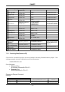
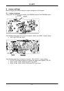
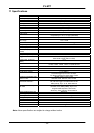
9.2 Jumper table
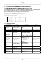
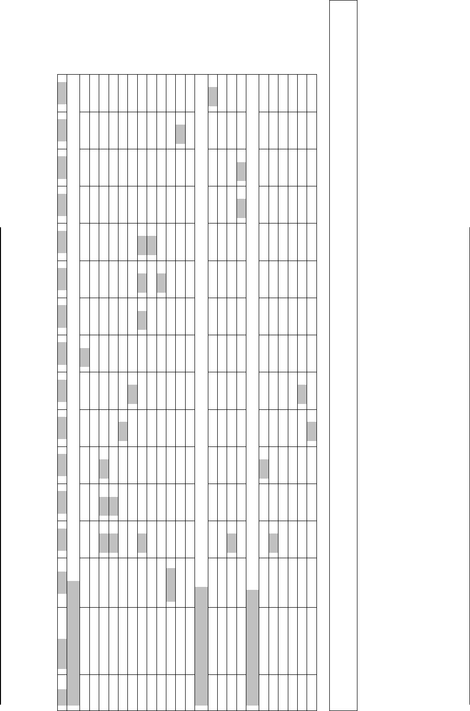
Jumper settings versus connector pin configuration.
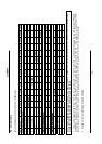
Pin# Function JP301 JP302 JP303 JP304 JP305 JP306 JP307 JP308 JP309 JP310 JP311 JP312 JP401 JP402
12-pin Hirose connector
6 Ext. HD input Short
6 Int. HD output Short
7 Ext. VD input Open Short Open
7 Ext. VD output Open Short
9 NC Open
9 PCLK output Short Open
10 WEN Open Short Short Open
10 NC Open Open
10 GND Open Short Short
11 Trigger Capacitor
11 NC Open Open
11 *) +12V DC Open Short
6-pin Hirose connector
4 NC Open
S
6 WEN Open Short Open
6 EEN Open Short
9-pin DSUB connector
1 NC Open
1 VD input Open Open Short
6 HD input Open
6 HD output Open
9 NC Open
9 PCLK output Open Short
4 GND hort
NOTE: When using the HD/VD, PCLK and WEN signals (input or output) from the 12 pin connector do not use the same signals (input
or output) from the 9 pin D-SUB connector and vice versa.
*) The external trigger pulse or DC +12V can be input at pin No.11 of the 12 pin Hirose connector by changing the jumper setting on PK8308
and PK8309. A capacitor is mounted at jumper JP301 to avoid feeding the trigger circuit with +12V DC. If this capacitor is removed from JP301
for some reason make sure JP301 is open before feeding the camera with +12V DC at pin No.11 of the 12 pin Hirose connector.
*) Greyed out jumper settings are factory settings.
- 22 -