


CV-M77
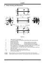
5 Pin Assignment
3
4
5
6
7
8
9
10
11
12
1
2
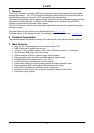
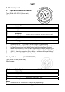
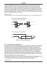
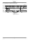
5.1 12-pin Multi-connector (DC-IN/SYNC.)
Type: HR10A-10R-12PB-01 (Hirose male)
Seen from rear.
Pin No. 5.1.1.1 Signal 5.1.1.2 Remarks
1
5.1.1.3 GND
2
+12V DC input
3
GND
4
NC
5
GND
6*
Ext.HD input
SW-S301.1 “ON” for 75Ω termination, SW-S303.1 “OFF” for HD output
7*
Ext.VD input
SW-S301.2 “ON” for 75Ω termination, SW-S303.2 “OFF” for VD output
8
GND
9*
NC
PCLK out: JP305 “short”, JP306 “open”
10*
WEN
NC: JP309 and JP310 “open”. GND: JP308 “open” JP309 and JP310 “short”
11*
Ext. trigger
NC: JP401 and JP301* “open”. +12V DC JP401 “short” and JP301* “open”
12
GND
Notes:
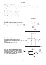
*) Signals on pin no. 6, 7,9,10 and 11 can be changed by jumper setting.
See section 8 “Switch Settings” and section 9 “Jumper Settings ” for more information.
*) In Edge Pre-select and Pulse Width Control mode do not input ext. VD signal.
*) When using the HD/VD, PCLK and WEN signals (input or output) from the 12-pin
connector do not use the same signals (input or output) from the 9 pin D-SUB connector.
*) JP301 is “short” by a capacitor (factory setting – see section 9 “Jumper Settings”.
*) Signals shown in bold italics are factory settings.
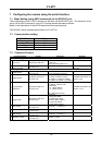
5.2 6-pin Multi-connector (RS 232C/TRIGGER)
Type: HR10A-7R-6PB (Hirose male)
Seen from rear.
Pin No. 5.2.1.1 Signal 5.2.1.2 Remarks
1
TXD (RS-232C)
2
RXD (RS-232C)
3
GND
4*
NC
GND: JP402 “short”
5
Ext.TRIG input
6*
EEN output
WEN out: JP312 “open” and JP311 “short”
Notes:
*) Signals on pin no. 4 and 6 can be changed by jumper setting.
- 7 -