


CV-M77
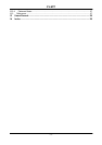
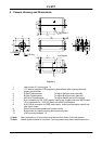
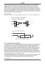
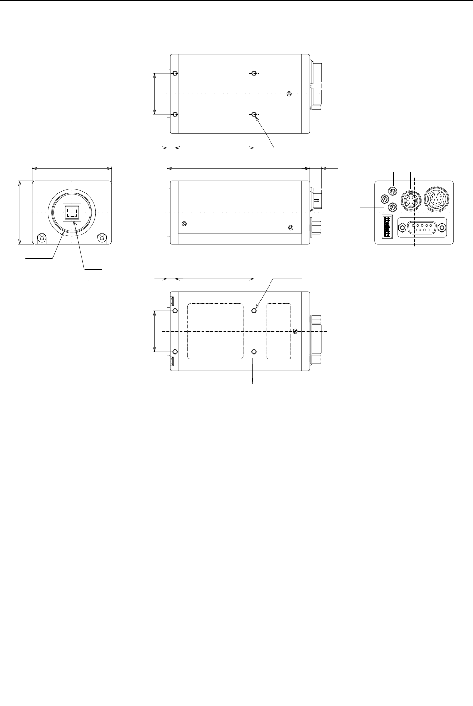
4 Camera Housing and Dimensions
SW1
(0.3)
(3.54)
(1.02)
(1.02)
(19.7)
(19.7)
(0.2)
(0.2)
(1.57)
(1.97)
1
(C-Mount)
4-M3 depth5
4-M3 depth5
26
5
50
7.6
90
5
50
26
40
50
SYNC/
RGB
DC
IN
TRIG
RS-232C
MG
B
R
2
(CCD chip)
7
6
4
3
5
8
11
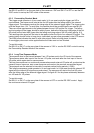
Figure 4-1
1 Lens mount of C-mount type. *1)
2 1/3" interline transfer CCD progressive scan sensor with square pixels and
primary mosaic filter
3 R Gain Potentiometer. To adjust Red gain level manually.
4 B Gain Potentiometer. To adjust Blue gain level manually.
5 MG Gain Potentiometer. To adjust Master gain level manually.
6 6 pin connector for RS 232C signals, input of ext. trigger pulse and WEN output.
7 12 pin connector for +12V DC power and HD/VD input/output.
8 9 pin D-Sub connector for RGB video output, video synchronization output and
pixel clock output.
9 Switch to set shutter speed and function mode.
10 Screw holes for tripod mounting plate (optional plate)
11 4 M3 mounting threads. *2)
*1) Note: Rear protrusion on C-mount lens must be less than 6mm (0.24-inch approx.)
*2) Note: Notice depth of thread is only 5mm. Too long screws may harm inside electronics.
- 6 -