


CV-A11
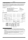
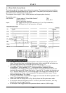
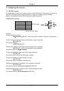
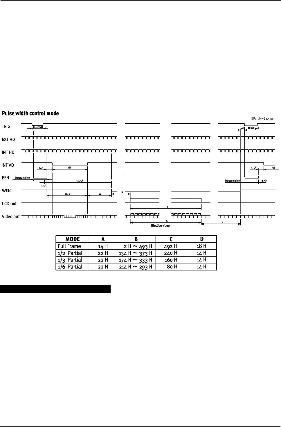
6.6. Pulse Width Control Mode
The leading edge of the trigger pulse initiates the capture. The exposure time (accumulation
time) is governed by the duration of the trigger pulse. If the polarity of this pulse is reversed,
the camera can be configured to correct for it.
The exposure time range is 1.5H to 1000H (shortest and longest pulse duration).
To use this mode:
Set function: Trigger mode to “Pulse Width Control” TR=2
HD accumulation HC=0, HC=1
Polarity and other functions
Input: Ext. trigger to pin 5 on 6 pin connector (or 11 on 12 pin connector)
Ext. HD to pin 6 on 12 pin connector. (If used).
Fig. 18. Pulse width control.
Important notes on using this mode:-
• The exposure will start and stop synchronized to the internal H signal. It result in 1H
jitter. To avoid this jitter, synchronize the camera with an external HD and make sure
that the trigger pulse aligns to the HD signal as shown in Fig. 14.
• This trigger mode is also supported by a function called “HD Asynchronous
Accumulation”, ACSII command “HC”. This function allows integration to start
immediately at the leading (falling) edge of the Ext. Trig pulse instead of at the next
horizontal drive pulse HD. Please refer to fig. 15 and fig. 16. To enable this function, set
HC=1. (Factory default is HC=0). If the falling edge of the trigger falls inside the HD low
pulse, a jitter up to 7.5µsec. can be expected. The exposure will start up to 7.5µsec.
after the falling edge of the trigger.
• In HD asynchronous PWC mode avoid the trigger to raise inside the HD low period. It will
cause 1 line image position jitter.
• Please note that the timing chart in Fig. 18 only shows the HD synchronous mode.
• Do not input external VD signal at Pin No. 7 of the 12-pin Hirose connector, as it may
disturb the external trigger function.
• Do not input a new trigger before the previous video is read out. (WEN is high).
- 10 -