


CV-A11
10. Appendix
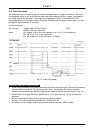
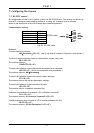
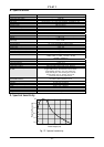
10.1. CV-A11 emulating CV-M10 interfacing
The CV-A11 has a slightly different pin configuration on the 12-pin Hirose connector, compared
to the M-series. This new configuration is compliant to the EIA-J standard. This means, however,
that the CV-A11 is not completely backward compatible with the CV-M10, CV-M40, etc in all
cases (depending on the cable configuration). The table below shows how to change the pin
configuration, by changing internal solder jumpers.
Please note: Only a qualified electronics technician or engineer should make these changes.
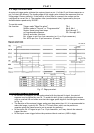
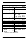
Hirose pin # Function JP2 JP3 JP5 JP1 JP4 Remarks
9 PCLK output enabled Short Note 2
9 No connection Open
10 WEN output Open Short
10 Connected to ground Short Open
11 Ext Trigger input Open Short
11 +12V DC in Short Open
Note 1: Configuration shown in Bold+Italic is factory default setting
Note 2: The RS-232C command “CW” must be set to CLK
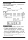
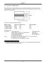
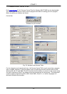
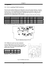
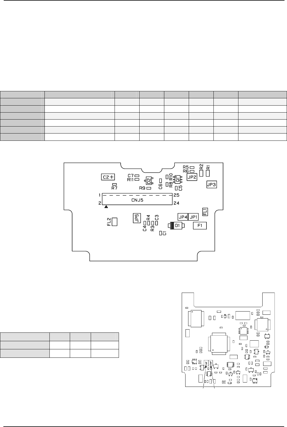
Fig. 28. PK8304 Rear Board of CV-A11
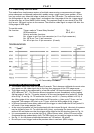
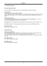
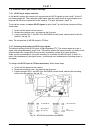
10.2. WEN out on pin 6 on 6 pin connector
JP1 JP2
Instead of EEN output on pin #6 on the 6 pin Hirose
connector, WEN can be output by jumper settings. The 2
jumpers are found on the main board PK8298B, if the
bottom plate is removed.
Signal on pin #6 JP1 JP2 Remar
k
EEN out Open Short default
WEN out Short Open
Bold+Italic is factory default setting
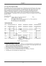
Fig. 29. PK8298A main board.
- 22 -