


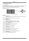
CV-A11
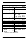
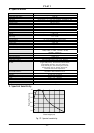
7.2. CV-A11 RS-232C command list.
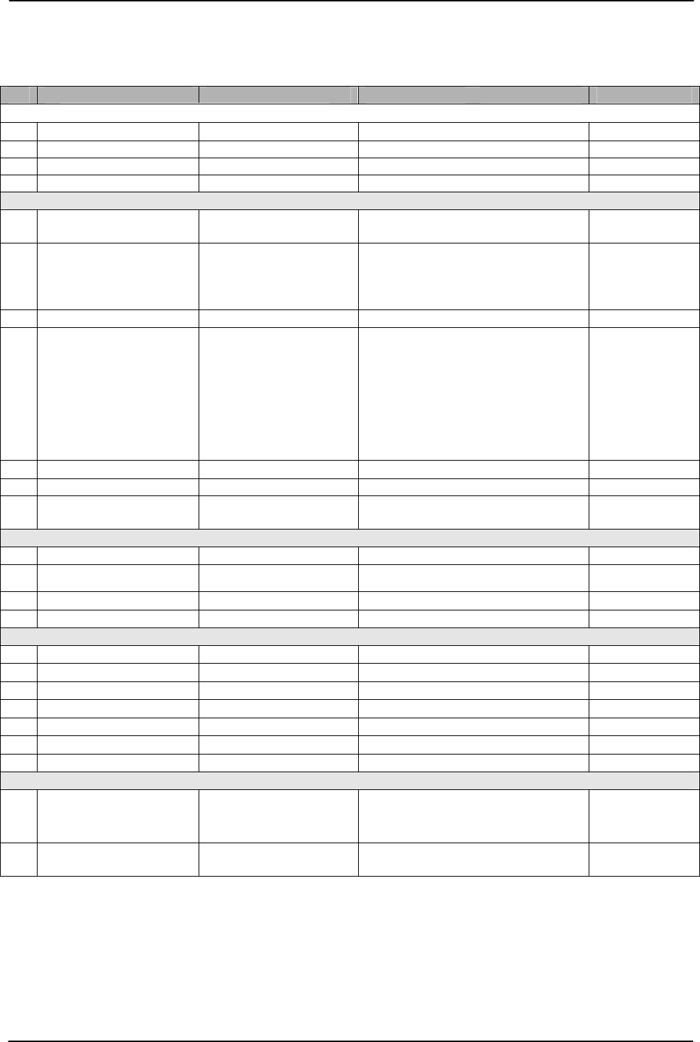
Command Name Format Parameter Remarks
A – General settings and useful commands
EB Echo Back
EB=[Param.]<CR><LF>
0=Echo off 1=Echo on
Off at power up
ST Camera Status request ST?<CR><LF>
Actual setting
HP Online Help request HP?<CR><LF>
Command list
VN Firmware version VN?<CR><LF>
3 letter version
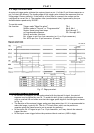
B – Timing and shutter related commands
SC Scanning format
SC=[Param.]<CR><LF>
0=full frame
2=1/3 partial
1=1/2 partial
3=1/6 partial
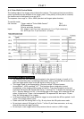
TR Trigger mode
TR=[Param.]<CR><LF>
0=normal
2=Pulse width
4=Long time
6=Smearless
1=Edge
3=Frame delay
5=Start/stop
SM Shutter mode
SM=[Param.]<CR><LF>
0=Normal 1=Programmab.
SH Shutter speed
SH=[Param.]<CR><LF>
0=1/30
2=1/60
4=1/250
6=1/1000
8=1/4000
10=1/20,000
12=1/60,000
14=1/100,000
1=1/50
3=1/125
5=1/500
7=1/2000
9=1/10,000
11=1/40,000
13=1/80,000
All15 step is valid
in normal trigger
mode.
In all trigger
modes shutter
speeds higher
than 9 will result
in 1/10,000
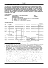
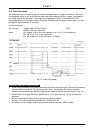
PE Programmable expos.
PE=[Param.]<CR><LF>
0=*1), 1=1.5H 1023=1023.5 H
H= 63.56µsec
HC HD accumulation
HC=[Param.]<CR><LF>
0=H synchron
accumulation
1=a-synchron
accumulation
a-sync. only for
TR=2 and TR=3
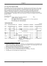
C – Signals and polarity
SO Sync signal
SO=[Param.]<CR><LF>
0=no sync 1=sync on video
CW Clock/WEN
CW=[Param.]<CR><LF>
0= WEN out 1=Clock out
CW=0 if clock not
used
TP Trigger polarity
TP=[Param.]<CR><LF>
0= active low 1= active high
*2)
WP WEN polarity
WP=[Param.]<CR><LF>
0= active low 1= active high
D – Gain and analogue signals setting
AS AGC Switch
AS=[Param.]<CR><LF>
0=AGC off 1=AGC on
0= manual gain
AG AGC Level
AG=[Param.]<CR><LF>
0=low 255=high
Range 0 to 255
GA Manual gain Level
GA=[Param.]<CR><LF>
0=low 255=high
Range 0 to 255
RP Rear Potentiometer
RP=[Param.]<CR><LF>
0=manual gain 1=rear potm.
SU Setup Level
SU=[Param.]<CR><LF>
0=low 255=high
Range 0 to 255
WC White clip Level
WC=[Param.]<CR><LF>
0=low 255=high
Range 0 to 255
GS Gamma Select
GS=[Param.]<CR><LF>
0=gamma 1 1=gamma 0.45
E – Saving and loading data in EEPROM
LD Load settings from
camera EEPROM
LD=[Param.]<CR><LF>
0=Factory data
2=User 2 area
1=User 1 area
3=User 3 area
Latest used data
area becomes
default at next
power up
SA Save settings to
camera EEPROM
SA=[Param.]<CR><LF>
1=User 1 area
3=User 3 area
2=User 2 area
*1) PE=0 has no function in triggered mode. PE=1 is 0.5H in continuous mode
*2) If positive logic is used (TP=1), the first trigger pulse after power up will be ignored.
!! Do not try to use commands not shown in the list.
- 18 -