


IIT Camera System Manual
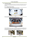
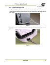
22 Installation
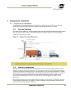
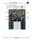
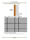
Figure 12. IIT I/O Board Power and Data Connector X2 signals
Table 1 Electrical Connections for the IIT Camera X2 connector
X2 Pin # Wire Color Signal
Remarks
1 White/Orange in Cat5E/6 cable
Ethernet A+
2 Orange in Cat5E/6 Cable
Ethernet A-
3 White/Green in Cat5E/6 Cable
Ethernet B+
4 Green in Cat5E/6 Cable Ethernet B-
5 White/Blue in Cat5E/6 Cable
Ethernet C+
Not Used
6 Brown in Cat5E/6 Cable Ethernet C-
Not Used
7 White/Brown in Cat5E/6 Cable
Ethernet D+
Not Used
8 Brown in Cat5E/6 Cable Ethernet D-
Not Used
9 Black (IN RED/BLACK PAIR) GND
10 Red (IN RED/BLACK PAIR) +24V DC
11 Pink (IN PINK/BLACK PAIR) Trigger Out+
Balanced Trigger Pulse Output
12 Black (IN PINK/BLACK PAIR) Trigger Out -
Balanced Trigger Pulse Output
13 Brown (IN BROWN/BLACK PAIR)
LS RS485+
Serial Trigger Command Output
14 Black (IN BROWN/BLACK PAIR)
LS RS485+
Serial Trigger Command Output
15 Orange (IN ORANGE/BLACK PAIR)
No Connection
16 White (IN ORANGE/BLACK PAIR)
No Connection
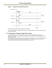
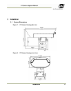
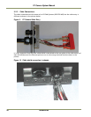
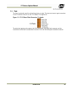
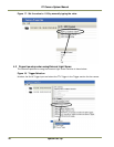
3.3 Connection to J-Panel and Power Supply
For connection to J-Panel please refer to VIS-CAM System Installation manual section 3.3.