


IIT Camera System Manual
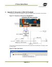
38 Appendix F
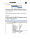
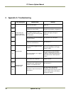
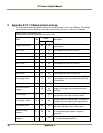
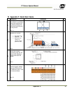
9 Appendix E: IIT I/O Board default settings
The table below shows the default settings for microcontroller U12 on the I/O Board. The settings
are accessible from the EN Setup via Serial Communication Terminal – Laser (IIT I/O Board).
Inquiry syntax: #<command><CR>
Change value syntax: #<command><hex-value><CR>
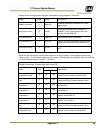
Name CMD
Value
Description
Hex
Dec
Trigger pulse width A 0A 10
Unit 0.1ms. Sets the pulse width of the trigger
pulse output
Dac 1 value C 32
50
Sets comparator level of channel 1
Dac 2 value D 32
50
Sets comparator level of channel 2
Dac 3 value E 32
50
Sets comparator level of channel 3
Dac 4 value F 32
50
Sets comparator level of channel 4
Dac 5 value G 32
50
Sets comparator level of channel 5
Dac 6 value H 32
50
Sets comparator level of channel 6
Dac 7 value I 32
50
Sets comparator level of channel 7
Dac 8 value J 32
50
Sets comparator level of channel 8
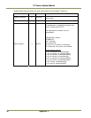
LS multiply factor K 01 01
Sets the first slope of the light sensor/ADC
curve together with LS divide factor up to the
LS knee point
LS divide facto
r
L 01
01
See description
K
s
Min time between
triggers
M C8
Depends
on
model
Unit 1ms. Sets the minimum time between two
triggers. No trigger can be generated within
this time.
LS knee point P 3A 58
Sets the point where the lightsensor/ADC curve
changes from first slope to second slope.
LS multiply 2 factor Q 03 03
Multiply factor for second slope. This factor is
multiplied by first slope to give second slope.
LS subtract value T 96 150
Offset for lightsensor/ADC curve. Below this
ADC value the light sensor value is zero.
Number of high
samples
X 06 06
Minimum number of successive 200μs samples
of no reflected signal before a trigger is
generated
Number of low
samples
Y 10 16
Minimum number of successive 200 μs samples
of no reflected signal before X