


IIT Camera System Manual
24 System Set-Up
4 System Set-Up
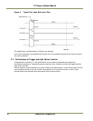
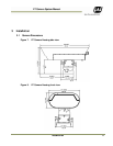
The proper way of deploying the camera, as described in section 4 of the VIS-CAM System
Installation manual, also applies to the IIT Camera.
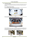
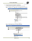
The Ethernet connection to the setup PC is accessed by removing the cable between the EN Camera
and the IIT I/O Board and connecting a RJ45 patch cable between the PC and the EN Camera. If the
PC does not have a gigabit Ethernet interface the RJ45 patch cable must be a crossover.
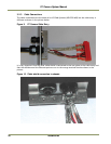
Note: Please do not make any adjustments of the camera mount inside the housing as this has been
adjusted from factory to the right position relative to the IR light coverage.
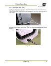
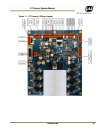
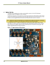
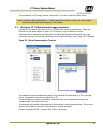
As a supplement the IIT I/O Board is equipped with a light emitting diode (LED) at each of the 8
fiber inputs. The LED is green when the reflected signal is detected from the fiber. When a license
plate is passing the reflection sensitive region of the scene one or more LED’s will be green. The
trigger is generated when the LED is turned off.
Figure 14. Signal Indicator LED positions