


1-9
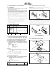
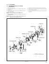
Fig. 1-5-1
1.5
5
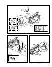
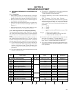
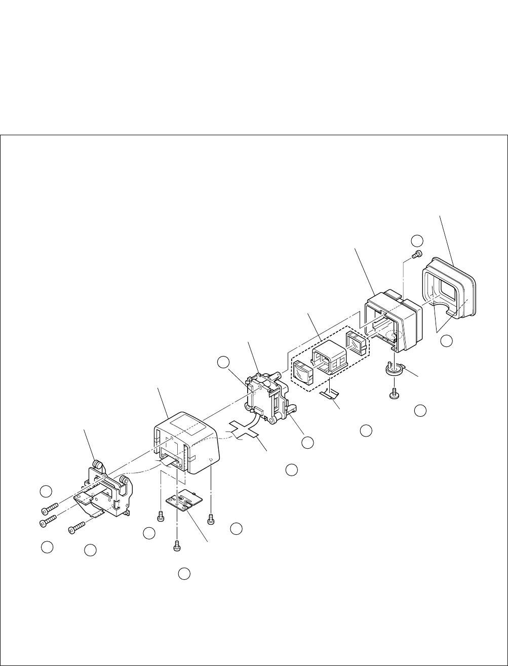
E. VF ASSEMBLY
1.5.1 Disassembly/assembly of E.VF assembly
(for the B/W VF)
1. Remove the EYE CUP.
2. Remove the three screws (1 to 3) and then remove the
CASE B (VF).
3. Remove the screw (4) to remove the LEVER (VF) and pull
out the LENS ASSY.
Note
5
a:
Be careful not to lose the SPRING (VF).
4. Remove the three screws (5 to 7) and then remove the
VF HINGE ASSY.
Note
5
b:
Be careful not to damage the FPC and not to
break any wires during the operation.
∗
: 0.078 N
•
m (0.8 kgf
•
cm)
(S a)
∗
1
EYE CUP
CASE A (VF)
5
(S b)
∗
4
5
(L b)
5
5
(L c)
5
(L a)
5
(S c)
∗
5
5
(S a)
∗
2
5
(S d)
∗
8
5
(S a)
∗
3
5
(S c)
∗
6
5
(S c)
∗
7
5
CASE B (VF)
VF HINGE ASSY
HOLDER LCD (VF)
LENS ASSY
FPC
LEVER (VF)
Note a
5
Note b
SPRING (VF)
CAP (VF)
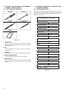
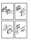
5. Remove the screw (8) and the remove the CAP (VF).
6. Remove the FPC from the CASE A (VF) so that the CASE
A (VF) may be unlocked.
7. Remove the HOLDER LCD (VF) while unlocking it by the
both side.