


1-1
(1) (2) (3) (4) (5)
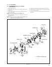
SECTION 1
DISASSEMBLY
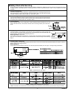
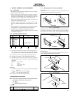
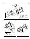
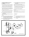
1.1.4 Disconnection of Connectors (Wires)
Connector
Pull both ends of the connector in the arrow direction, re-
move the lock and disconnect the flat wire.
1.1 BEFORE ASSEMBLY AND DISASSEMBLY
1.1.1 Precautions
1. Be sure to remove the power supply unit prior to mount-
ing and soldering of parts.
2. When removing a component part that needs to discon-
nect the connector and to remove the screw for remov-
ing itself, first disconnect the connecting wire from the
connector and then remove the screw beforehand.
3. When connecting and disconnecting the connectors, be
careful not to damage the wire.
4. Carefully remove and handle the part to which some
spacer or shield is attached for reinforcement or insula-
tion.
5. When replacing chip parts (especially IC parts), desolder
completely first (to prevent peeling of the pattern).
6. Tighten screws properly during the procedures.
Unless specified otherwise, tighten screws at a torque
of 0.088N
•
m(0.9kgf
•
cm).
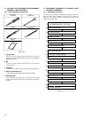
1.1.2 Assembly and disassembly
(1) Indicate the disassembly steps. When assembling, per-
form in the reverse order of these steps. This number
corresponds to the number in the disassembly diagram.
(2) Indicates the name of disassembly/assembly parts.
(3) Indicates the number in the disassembly diagram.
(4) Indicates parts and points such as screws, washers,
springs which must be removed during disassembly/
assembly.
Symbol Name, Point
S Screw
L Lock, Pawl, Hook
SD Soldering
(Example)
•2 (S
1
): Remove the two screws (S
1
) for removing the
part 1.
•CN
1
: Disconnect the connector
1
.
•SD
1
: Unsolder at the point SD
1
.
(5) Precautions on disassembly/assembly.
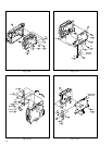
1.1.3 Destination of connectors
Note:
Three kinds of double-arrows in connection tables re-
spectively show kinds of connector/wires.
↔ : Wire
⇔ : Flat wire
: Board to Board connector
[Example]
Fig. 1-1-1 Connector 1
Connector
Flat wire
Fig. 1-1-2 Connector 2
Connector
Flat wire
Extend the locks in the direction of the arrow for unlocking
and then pull out the wire. After removing the wire, immedi-
ately restore the locks to their original positions because
the locks are apt to come off the connector.
B-B connector
Pull the board by both the sides in the direction of the ar-
row for disconnecting the B-B connector.
Fig. 1-1-3 Connector 3
Connector
Connector
Fig. 1-1-4 Connector 4
Connector
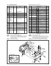
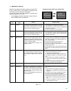
CONN.
No.
Pin No.
CONNECTOR
CN
1
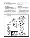
MAIN CN101 ⇔ MONITOR CN761 40
UPPER CASE
ASSY
(Inc. MONITOR
ASSY / E.VF
ASSY)
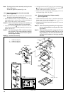
DSC BOARD
ASSY
COVER (HINGE)
STEP
No.
PART
Fig.No.
POINT NOTE
Fig. 1-3-1
Fig. 1-3-2
5(S1a), 4(S1b), 3(S1c),
CN1
(S2), CN2a, CN2b
2(S3)
–
–
–
1
/
2
3
----------------- --------------------------------------