


1-2
$
6
3
4
0
!
@
#
%
/
^
5
1
/
2
7
/
8
/
9
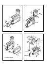
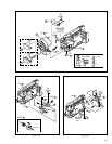
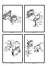
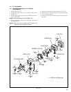
UPPER CASE ASSY
(Inc. MONITOR ASSY / E.VF ASSY)
DSC BOARD ASSY
COVER (HINGE)
MONITOR ASSY
E.VF ASSY
MONITOR BOARD ASSY
FRONT ASSY
(Inc. DC LIGHT, MIC )
DC LIGHT / LIGHT COVER
MIC
OP BLOCK ASSY
REAR UNIT ASSY
LOWER CASE ASSY
JUNCTION BOARD ASSY
MAIN BOARD ASSY
JACK BOARD ASSY
MECHANISM ASSY
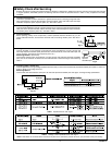
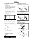
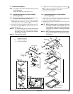
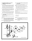
1.2 JIGS AND TOOLS REQUIRED FOR DISASSEMBLY,
ASSEMBLY AND ADJUSTMENT
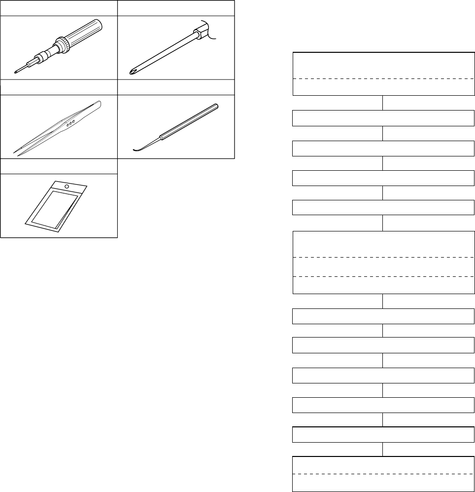
1.2.1 Tools required for adjustments
1. Torque driver
Be sure to use to fastening the mechanism and exterior
parts because those parts must strictly be controlled for
tightening torque.
2. Bit
This bit is slightly longer than those set in conventional
torque drivers.
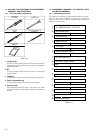
3. Tweezers
To be used for removing and installing parts and wires.
4. Chip IC replacement jig
To be used for adjustment of the camera system.
5. Cleaning cloth
Recommended cleaning cloth to wipe down the video
heads, mechanism (tape transport system), optical lens
surface.
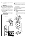
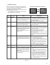
1.3 DISASSEMBLY/ASSEMBLY OF CABINET PARTS
AND BOARD ASSEMBLY
1.3.1 Disassembly flow chart
This flowchart indicates the disassembly step for the cabi-
net parts and board assembly in order to gain access to
item(s) to be serviced. When reassembling, perform the
step(s) in reverse order.
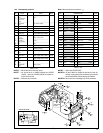
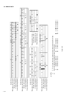
Table 1-2-1
Table 1-3-1
Torque Driver
YTU94088
1
Bit
YTU94088-003
2
3
Chip IC Replacement Jig
PTS40844-2
4
5
Cleaning Cloth
KSMM-01
Tweezers
P-895