


3-1
SECTION 3
ELECTRICAL ADJUSTMENT
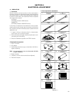
3.1 PRECAUTION
1. Precaution
Both the camera and deck sections of this model needs a
personal computer for adjustment except simple adjustment
with potentiometers. If some of the following parts is replaced
for repair or other reason, the repaired set must be adjusted
with a personal computer.
• OP block
• E
2
PROM (IC1003 of MAIN board)
• MONITOR
• E
2
PROM (IC7603 of MONITOR board)
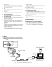
In the event of malfunction with electrical circuits, trouble-
shooting with the aid of proper test instruments most be done
first, and then commence necessary repair, replacement and
adjustment, etc.
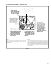
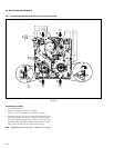
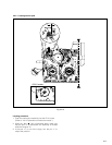
1. In case of wiring to chip test points for measurement,
use IC clips, etc. to avoid any stress.
2. Since connectors are fragile, carefully handle them in dis-
connecting and connecting.
3. Shortcircuit between operation and DECK chassis.
2. Required test equipment
1. Color TV monitor.
2. AC adapter
3. Oscilloscope (dual-trace type, observable 100 MHz or
higher frequency)
Note :
It is recommended to use one observable 300 MHz
or higher frequency.
4. Digital voltmeter
5. Frequency counter (with threshold level adjuster)
6. Personal computer
Table 3-1-1
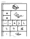
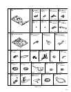
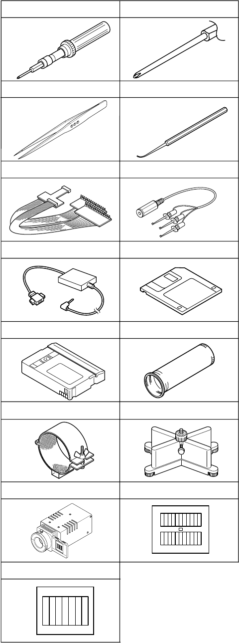
3. Tools required for adjustments
Torque Driver
YTU94088
1
Bit
YTU94088-003
2
Service Support System
YTU94057-57
10
INF Adjustment Lens
YTU92001B
11
INF Adjustment Lens Holder
YTU94087
12
Camera Stand
YTU93079
13
Light box Assembly
YTU93096A
14
Gray Scale Chart
YTU94133A
15
Color Bar Chart
YTU94133C
Communication Cable
YTU93107A
7
PC Cable
QAM0099-002
8
Alignment Tape
MC-1
9
3
Chip IC Replacement Jig
PTS40844-2
4
Tweezers
P-895
Jig Connector Cable
YTU93082C
5
6