9
Connections
Notes:
• Use the above composition of device or its equivalent.
• Do not connect this camera to equipment other than that depicted in these connection diagrams.
• When connecting monitors, VTR, etc to the camera control unit, please rely on a qualified serviceman to check that the
increased current leakage does not surpass the regulated level, during initial connection.
• If the isolation transformer cabinet is corroded, please approach your local authorized dealer to have it replaced.
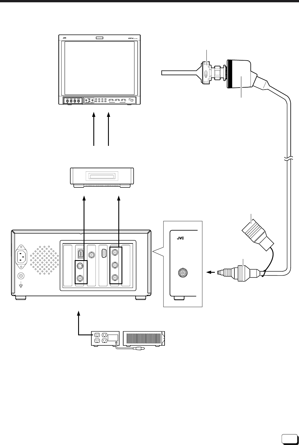
L Connection example
~AC IN
NTSC OUT SXGA OUT
GBR
DV Y
PB
PR
Y/C
(S)
VBS
HD OUT
GENLOCK
IN/OUT
Endoscope
(Commercially
available)
Endoscope adapter (Optional)
Connector Cap
Connector
Camera
head
DT-V1900CG (Optional)
SR-W7MAU (Optional)
(W-VHS)
Front
To each
equipment
Isolation transformer AA-V31U (Optional)
Video
S(Y/C) Out
(Y, P
B
, P
R
) Out
AC 120V
HD
CAMERA
VOLUME
SLOT 1
A
B
DEGAUSS
MENU
MUTING
SCREENS
CHECK
ASPECT
AREA
MARKER
UNDER
SCAN
PULSE
CROSS
COLOR
OFF
SLOT 2
C
D
SLOT 3
POWER
E
F
INPUT SELECT


