


E-8
1
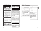
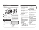
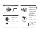
Power Supply cable
To input DC 12 V or AC 24 V power.
The AC 24 V power supply should
conform to the following:
U-type: Class 2 only
E-type: Isolated power supply only
2
Video signal output connector (BNC)
This BNC connector outputs a composite
video signal. Connect this to the video
input connector of a video monitor,
switcher, etc.
3
Safety cable
This wire is mounted to the ceiling slab
or channel. (Safety cable not included.)
4
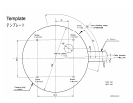
Mounting holes
These holes are used to mount the
camera body to the ceiling. When using
a 4 inch square electrical box, the 2 holes
diagonally across are used to fix the box
in place.
( ੬ page 13)
5
Cable extraction hole
This hole is used to extract cables from
the side of the camera without opening
holes in the ceiling.
6
Cover
This cover is removed to pull the cables
through the
5
cable extraction hole.
Replace the cover after pulling the
cables.
7
Cover locking screw
This screw is removed when removing
the
6
cover.
Introduction
Names and Operations of Parts (continued)
3
2
1
4
5
6
7
7
4
Main unit side
Ⅲ Body Underside
CAUTION:
To avoid unforeseen accidents, attach the
safety cable. Otherwise, there is nothing
to prevent the camera from falling should
it come loose.
E-9
English
REC
PLAY
FFREW
REVERSE
PAUSE/
STILL
REC
CHECK
STOP/EJECT
COUNT/
CLOCK
TIME
MODE
TIMER
REC
AL/PL
RESET
MENU
VIDEO CASSETTE RECORDER
SHIFT/TRACKING
SET/V.LOCK
RESET
/CANCEL
OPERATE
SR-L910E
OPE. LOCK
1
TO CAMERA
TO CAMERA
DATA I / O
DATA I / O
RX
RX
+
RX
RX
-
TX
TX
+
TX
TX
-
COM
COM
1 2 3456 7 8
COM
COM
9/110/211/312/4 13/514/615/716/8
16/8
COM
COM
COM
COM
COM
COM
CAMERA
CAMERA
SW
UNIT
UNIT
ALARM
ALARM
AUTO
AUTO
4312 875 6
2 3 4 5 6 7
8
1
MONITOR
MONITOR
OUTPUT
OUTPUT
MONITOR
SERIAL-2
SERIAL-2
SERIAL-1
VIDEO INPUT
VIDEO OUTPUT
OUTPUT
OUTPUT
2
1
ON
ON
2 3 4 5 6 7
8
POWER
OFF
ON
AC INPUT
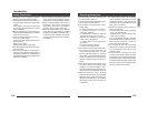
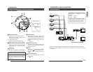
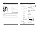
System diagram
Installation and connection
•Turn OFF the power supply to all equipment to be used before making connections.
• Read the Instruction Manual for each piece of equipment to be used before making
connections.
Camera 1
Video signal
Power
Camera 2
Video signal
Power
Camera 3
Video signal
Power
Camera 4
Video signal
Power
Power Unit
DC 12 V or AC 24 V
Switcher, etc.
MONITOR
OUTPUT 1
MONITOR
OUTPUT 2
MONITOR
MONITOR
DVR, etc.
VIDEO IN
MEMO
Power supply necessary for one
TK-C205
DC 12V : 300mA
AC 24V : 280mA
• When the voltage drops due to fluctua-
tions in voltage or compatibility with the
power supply cable, the current in-
creases by 30% for each TK-C205.
VIDEO
INPUT