


E-10
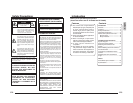
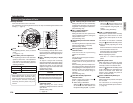
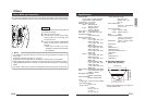
Ⅲ Video signal cables
Connect the coaxial cables (BNC) to the video
signal output connector (BNC).
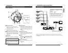
About Connection Cables
Installation and connection
Ⅲ DC 12 V or AC 24 V power supply cable
Connect the DC 12 V or the AC 24 V power
supply to the DC 12V/AC 24V terminals on
the terminal board. To prevent connection
errors or a cable disconnection, we recom-
mend the use of lug plates for the connec-
tions.
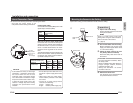
The following table shows the connection dis-
tances and connection cables provided that
2-conductor VVF cables (vinyl-insulated vi-
nyl sheath cables) are used.
• Do not allow input from both a DC 12 V
and AC 24 V power supply at the same
time.
• When using a DC 12 V power supply,
ensure that the polarities of the cable
are correct.
•The AC 24 V power supply should
conform to the following:
U-type: Class 2 only
E-type: Isolated power supply only
Be careful of the following items when connecting the cables.
CAUTION:
• If thin cables are used (i.e. with a high
resistance), a significant voltage drop
will occur when the unit is at its
maximum power consumption. Either
use a thick cable to restrict the voltage
drop at the camera side to below 10%,
or place the power supply near to the
camera. If voltage drop occurs during
operation, the performance will be
unstable.
To Video
Signal Cable
To DC 12 V or
AC 24 V
Power Supply
•Turn OFF the power supply to all
components before making connections.
Conductor diameter (mm)
ø1.0mm ø1.6mm ø2.0mm
(AWG18) (AWG14) (AWG12)
DC 12V 60m 160m 250m
(200ft) (520ft) (820ft)
AC 24V 150m 400m 600m
(490ft) (1300ft) (2000ft)
Maximum
extension (m)
Cable
Maximum extension (No cable
compensator)
RG-59 200m
RG-6 350m
RG-11 450m
E-11
English
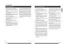
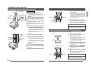
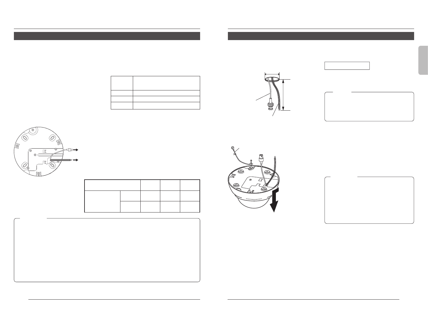
Mounting the Camera to the Ceiling
φ
20 mm
Approx.10 cm
Video signal
cable
Power supply cable
1.
2.
Safety cable
3.
4.
Open hole in ceiling, connect cables and mount camera to ceiling.
Preparations
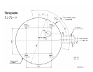
1.
Open a hole in the ceiling.
Use the template and open a hole in the
ceiling for the cables.
MEMO
There is no need to open a hole in the
ceiling when using the cable extraction
hole on the side of the camera.
( ੬ page 8)
2.
Pull out the cables from the ceiling.
Before connecting, pull out the power
supply and video signal cables about
10 cm from the ceiling.
3.
Attach the safety cable to the cam-
era. (Safety cable not included)
Attach the safety cable to the back of
the camera.
CAUTION:
•To avoid unforeseen accidents, attach
the safety cable.
•Select a suitable safety cable based on
length, strength, location, material
(insulation property), etc.
•Always use the M2.6
× 6 screws
mounted on the unit.
4.
Remove the dome cover.
Turn the dome cover counterclockwise
and pull downwards to remove.