


11
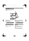
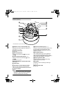
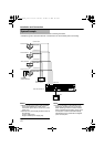
Camera (Interior)
M Rotation Knob ( TK-C215VP4U/E only)
Rotate the lens unit to adjust the inclination of
the image. (A Pg. 25)
N
Rotation Center Mark
(A Pg. 25)
O Fall Prevention Wire
Use this to connect the base G to the dome
cover D.
P Camera Unit Fastening Screw ן 2
Use this to fasten the camera body R to the
base G.
To remove (A Pg. 21)
Q [MONITOR]Monitor Terminal (RCA Jack)
(A Pg. 25)
R Camera Unit
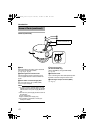
S Connector for Power Supply of Heater
This is a power connector for use when the
heater (sold separately: KA-ZH215) is mounted.
T Space for Heater
Memo:
● When mounting the heater (sold separately:
KA-ZH215), read the instruction manual of
the heater carefully before mounting.
U Camera Unit Fastening Clip ן 2
This clip is used for fastening the camera unit to
the base. When removing the base, press
toward the direction indicated by the arrow to
release. (A Pg. 21)
V Tilt Fastening Screw
Upon adjusting the angle of view, tighten the
screw to ensure that camera’s angle of view
does not go out of alignment when it is used at a
location with strong vibration. (A Pg. 25)
W Shooting Direction Mark
Install the camera by aligning the shooting
direction with the arrow mark.
X Lug Plate
This plate is used for fastening the silica gel.
(A Pg. 24)
Y Space for Silica Gel
(A Pg. 24)
Q
R
S
M
N
V
W
X
P
Y
O
T
U
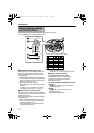
Lens
(A next page)
*TK-C215VP4U/E is used in the above illustration
TK-C215VP4_JP.book Page 11 Thursday, November 2, 2006 10:51 AM