


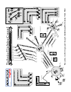

CONTROLS IN DETAIL, CONTINUED
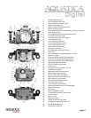
27. LATCHES: Two heavy duty latches with safety locks to protect against accidental opening.
28. MOUNTING HOLE FOR ACCESSORY: a 1/4”-20 TPI hole is supplied to accept a TLC accessory or TLC base ball for
mounting a strobe arm or a modeling light.
29. REMOVABLE VIEWFINDER: A full view of the illuminated camera viewnder displays all necessary information.
This viewnder can be removed and replaced with the optional Aqua View Finder (# 20054) for a larger displayed image.
30. METERING PATTERN SELECTOR KNOB: Push and rotate clockwise or counter clockwise to select the metering mode,
Spot, Center Weighted or Matrix metering options.
31. MULTI SELECTOR CENTER / RECORD BUTTON: press to record in video mode or to accept selection while
scrolling menus.
32. AE / AF LOCK & AF-ON LEVER: Lock the auto focus / auto exposure or use for activating the AF-ON button according
to preference. See page 9 for more info (these button can also be re assigned to other functions via CSM menu of camera).
33. MAIN-COMMAND INPUT KNOB: It rotates clockwise and counterclockwise. It can be used alone or in combination with other
controls to select or set various camera functions or modes. Refer to camera manual for in depth use.
34. MULTI SELECTOR BUTTONS: These buttons have multiple uses. They allow the selection of the focus area, in the menu
mode, they are used to scroll up or down and left to right to choose from your menu selection and they are used as well in the
delete mode.
35. AUTOFOCUS MODE SELECTOR KNOB: It rotates clockwise and counterclockwise. Use it to select the various auto focus
pattern available. Refer to camera manual for in depth use.
36. INFO BUTTON: This button will activate the rear LCD and display all pertinent shooting information, this function can also be
accessed through the ON/OFF/Illuminator knob (see shooting tip on page 9)
37. LV BUTTON: Press to activate the Live View function of the camera (required for video mode).
38. MOISTURE ALARM WARNING DIODE: Warning LED will light up in the unlikely event of water penetrating the housing.
39. MONITOR DISPLAY WINDOW: allow viewing of menus, information and images
40. OK BUTTON: Press to acknowledge selected function.
41. ZOOM MAGNIFIER BUTTON: Press to enlarge image on LCD, use with Main dial command to navigate through the image.
42. THUMBNAIL/PLAYBACK BUTTON: Press to display images in “contact sheets” of 4 or 9 images or for zooming out.
43. PROTECT BUTTON: Press to protect selected image from accidental deletion.
44. MENU BUTTON: Press to activate menu display, scroll using multiple selector buttons and select using enter button.
45. PLAYBACK BUTTON: Press to activate the monitor and review images.
46. DELETE BUTTON: Press to delete images, use multiple selector buttons to select and press the enter button to delete, can
also be used in conjunction with the mode selector button (24) in order to format the card inside the camera.
47. MOUNTING HOLES: Three 1/4” X 20 holes are provided for mounting strobes trays or accessories.
48. SACRIFICIAL ANODES: (2X) zinc anodes are installed to protect your housing against salt water corrosion; theses are made
to deteriorate faster than the other strategic part of your housing, hence the name sacricial anodes. These anodes need to be
replaced by the user as needed.
49. RUBBER ANTI SKID PADS: Four rubber pads are provided to protect the housing and preventing it from sliding on wet decks.
page 4