–14–
Controls and Their Functions
Shooting (Recording)/Playback Function Section (1)
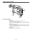
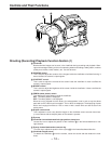
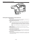
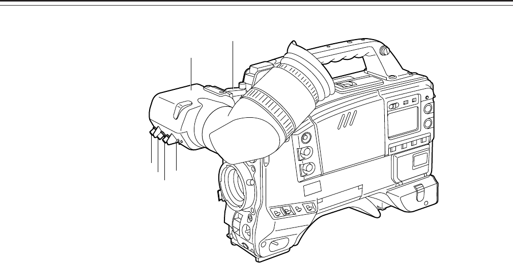
¢ Viewfinder
Black-and-white images can be seen in the viewfinder during recording and playback. Warn-
ings and messages relating to the unit’s operating status and settings, zebra pattern, markers
(safety zone marker, center marker), etc. can also be seen.
£ PEAKING control
This is used to adjust the contours of the images inside the viewfinder to facilitate focusing. It
does not affect the camera’s output signals.
§ CONTRAST control
This is used to adjust the contrast of the screen inside the viewfinder. It does not affect the
camera’s output signals.
• BRIGHT control
This is used to adjust the brightness of the screen inside the viewfinder. It does not affect the
camera’s output signals.
¶ ZEBRA (zebra pattern) switch
This displays the zebra pattern inside the viewfinder.
ON: The zebra pattern is displayed.
OFF: The zebra pattern is not displayed.
When the unit is shipped from the factory, the zebra pattern is set in such a way that those
parts with an IRE video level from approx. 70% to 85% are displayed. The displaying of parts
with a level ranging from 50% to 110% or more or with a certain level can also be set on the
setting menu.
ß Diopter control knob
This is adjusted in such a way that the images on the viewfinder screen are seen most clear-
ly in accordance with the dioptric power of the camera’s operator.
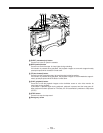
® Eye cup
© Viewfinder forward-backward/left-right position clamp lever
Loosen this lever to adjust the position of the viewfinder ¢ in the forward-backward or left-
right direction.
™ Eyecup forward-backward movement ring
Turn this ring to adjust the position of the eyecup ® in the forward-backward direction.
´ Viewfinder stopper screw
To detach the viewfinder ¢ from the camera, loosen this screw and then detach the view-
finder.
£
§
•
¶
¢
©


