12
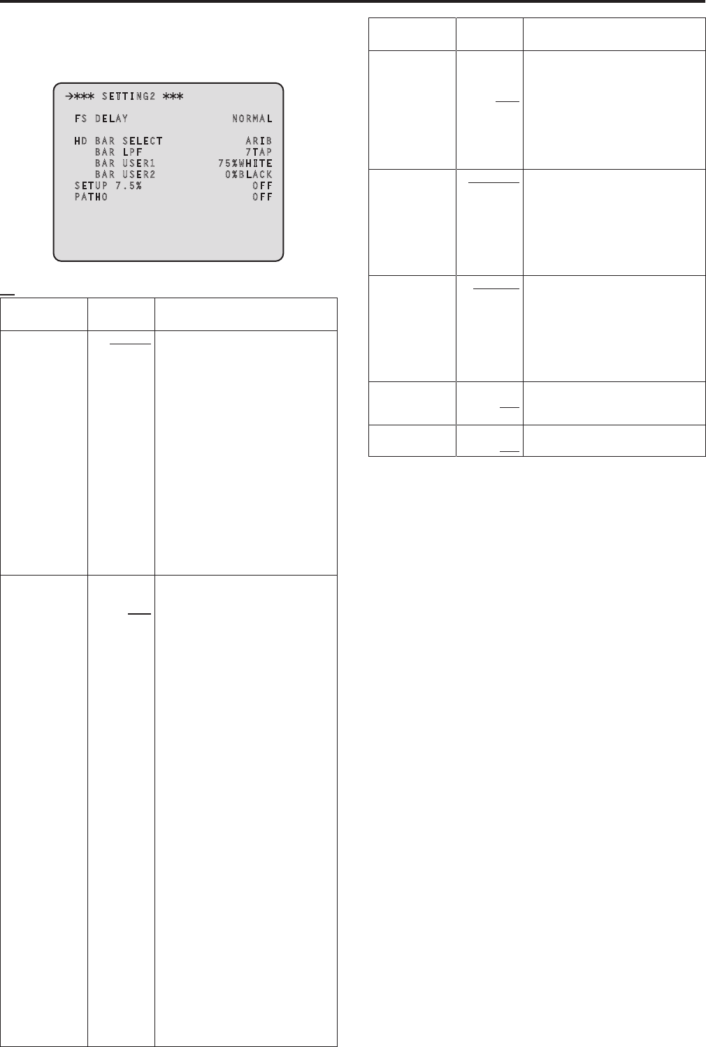
SETTING2 Screen
This is the selection screen for the SETTING2 menu
Moving the cursor to the “SETTING2” menu title and then pressing the
SELECT dial redisplays the OPERATION menu one level up
SETTING2
FS DELAY NORMAL
HD BAR SELECT ARIB
BAR LPF 7TAP
BAR USER1 75%WHITE
BAR USER2 0%BLACK
SETUP 7.5% OFF
PATHO OFF
indicates the factory default setting
Item
Setting
value
Remarks
FS DELAY
NORMAL
SHORT
Select the delay mode for the HD return
signals
NORMAL:
Matches return signal input that does
not match the sync phase to the
phase of the camera by delaying it by
1 frame
SHORT:
Sets the shortest delay (5 H)
However, if the following conditions
are not met, it is delayed by
1 frame + 5H
HD signal
The SD-HD V item in the HD/SD
PHASE screen is “ADVANCE” or
“0H_SD_DLAY”
When output from this unit is used
as the return signal, the delay is
less than 3H
HD BAR SELECT
FULL
BARS-1
ARIB
BARS-2
BARS-3
BARS-4
BARS-5
BARS-6
Select the color bar signals to be output
from the HD/SD SDI OUT connectors
and VBS connector when “BAR” has
been selected on the operation panel
of the ROP
When they are output in VBS or SD
format, color bars in HD format are
output in the mode specified with
DOWNCONVERT MODE*
FULL:
75 % full field color bar
BARS-1:
Color bar based on the SMPTE
standard
ARIB:
ARIB multi-format color bar
BARS-2:
Color bar based on the EIAJ standard
BARS-3:
Split field color bar
BARS-4:
75 % full field color bar placed in an
area with a 4:3 aspect ratio
(Displayed 40 % gray outside the
area)
BARS-5:
Color bar based on the SMPTE
standard that is placed in an area
with a 4:3 aspect ratio
(Displayed 40 % gray outside the
area)
BARS-6:
Color bar based on the EIAJ standard
that is placed in an area with a 4:3
aspect ratio
(Displayed 40 % gray outside the
area)
Item
Setting
value
Remarks
BAR LPF
OFF
3TAP
5TAP
7TAP
9TAP
Select the filter through which to pass
the color bar signals to be output
from the HD/SD SDI OUT connectors
when BAR has been selected on the
operation panel of the ROP
A higher TAP value will ensure a
smooth rise and fall of the waveforms
and reduce both the overshoot and
undershoot
BAR USER1
75%WHITE
100%WHITE
+I_SIGNAL
–I_SIGNAL
Set user range 1 for when ARIB has
been selected as the HD BAR SELECT
setting
This can be set when “ARIB” is selected
for the HD BAR SELECT item
In the case of another setting, “——”
is displayed and a setting cannot be
selected
BAR USER2
0%BLACK
+Q_SIGNAL
Set user range 2 for when ARIB has
been selected as the HD BAR SELECT
setting
This can be set when “ARIB” is selected
for the HD BAR SELECT item
In the case of another setting, “——”
is displayed and a setting cannot be
selected
SETUP 75%
ON
OFF
Select whether to add the setup 75 %
level to the SD signals to be output from
[OUT/PM] of the VBS connectors
PATHO
ON
OFF
Select ON/OFF for the pathological
signals
*: The DOWNCONVERT MODE setting can be configured by operating
the REMOTE OPERATION menu with the ROP
For details, refer to Operating Instructions <Operations and Settings>
of AK-HRP200
Setting menu items (Continued)


