


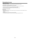
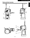
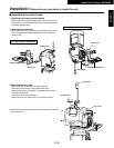
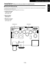
1Rotary head
This rotates in the horizontal direction.
2Pedestal
3POWER ON/OFF switch
When this is set to ON, the unit’s power is turned on;
when it is set to OFF, it is turned off.
4
AC 100 inlet [AC IN] (AC 3-point inlet)
Connect the accessory AC power cable to this inlet.
5
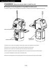
Camera mounting base mounting screws
M5!20 mm hexagon socket head screws, M5 flat
washers (3 of each provided as accessories)
These parts are used to secure the camera mounting
base to the rotary arm.
6
Tally lamp (accessory)
This is lit up red by the selected signals.
7
Rotary arm mounting screws
M5!20 mm hexagon socket head screws, M5 flat
washers (4 of each provided as accessories)
These parts are used to secure the rotary arm to the
rotary head.
8
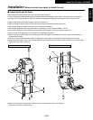
Rotary arm
This rotates in the vertical direction.
9
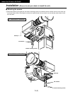
Camera mounting base
Mount the convertible camera on this base.
:Pan/tilt head mounting holes
These four holes are used when installing the pan/tilt
head.
;Bottom panel
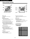
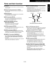
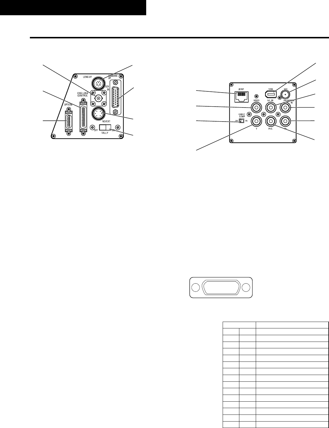
<PROMPTER connector
The prompter is connected to this connector.
The maximum current which can be supplied from the DC
12V OUT socket is 2A.
When the prompter is connected, the pan/tilt head’s
speed is reduced to about one-third.
Indoor Pan/Tilt Head AW-PH400
7(E)
Parts and their function
C
D
A
@
B
G
H
I
J
K
L
M
N
O
P
E
F
Pin No. Signal Name
1 – – –
9 PROMPTER VIDEO GND
2 PROMPTER VIDEO
10 – – –
3 – – –
11 – – –
4 DC 12V OUT
12 GND
5 – – –
13 – – –
6 – – –
14 DETECT
7 – – –
15 GND
8 – – –
87654321
?>=<;:9
Pin layout as seen facing the
prompter connector
Rotary head connector panel Pedestal connector panel