


-9-
Cautions:
• Keep the DC Power ON / OFF switch in the OFF
position until all connections have been properly
made.
• Connect the enclosed camera head and the cam-
era control unit in the same package. Connecting
other models may cause malfunctions.
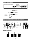
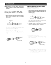
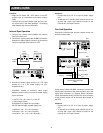
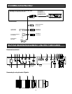
Internal Sync Operation
1. Connect the camera cable between the camera
head and control unit.
2. Connect the coaxial cable with the BNC connectors
between the Video Output Connector of the camera
control unit and the video monitor or VTR.
3. Connect the power cable from the 12 V DC input
terminal to a 12 V DC power supply unit (pur-
chasable locally).
• Calculation method of maximum cable length
between camera control unit and the power supply
unit is as follows:
11.5V DC < VA - (R x 0.42 x L) < 16V DC
L: Cable length (meter)
R: Resistance of copper wire (Ω / meter)
VA: DC output voltage of power supply unit
L standard = VA – 12 / 0.42 x R (meter)
L minimum = VA – 16 / 0.42 x R (meter)
L maximum = VA – 11.5 / 0.42 x R (meter)
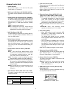
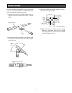
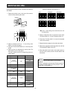
Using coaxial cables with BNC connectors, connect the
video output connector of the camera control unit to the
video input connector of a Special Effects Generator
(SEG) (purchasable locally) and the G/L input connector
of the camera control unit to the black burst output of
the SEG.
Cautions:
• Connect this to a DC 12 V class 2 power supply
only.
• To prevent fire or electric shock hazard, the UL list-
ed wire VW-1 style 1007 should be used for the
cable for DC 12V Input Terminal.
Cautions:
• Connect this to a DC 12 V class 2 power supply
only.
• To prevent fire or electric shock hazard, the UL list-
ed wire VW-1 style 1007 should be used for the
cable for DC 12V Input Terminal.
Gen-lock Operation
Connect the camera head and the camera control unit
with the camera cable.
IN
OUT
VIDEO
Hi-Z75Ω
IN
OUT
VIDEO
Hi-Z75Ω
S-VIDEO OUT
VIDEO OUT G/L IN
OFF
ON
75
Ω
EVR
1
2
3
4
5
6
7
8
9
0
1
2
3
4
5
6
7
8
9
0
DC 12V IN
RGB/SYNC OUT
Video
Monitor
VTR or
Video Monitor
Coaxial
Cable
CCU
S-VIDEO OUT
VIDEO OUT G/L IN
OFF
ON
75
Ω
EVR
1
2
3
4
5
6
7
8
9
0
1
2
3
4
5
6
7
8
9
0
DC 12V IN
RGB/SYNC OUT
S-VIDEO OUT
VIDEO OUT G/L IN
OFF
ON
75
Ω
EVR
1
2
3
4
5
6
7
8
9
0
1
2
3
4
5
6
7
8
9
0
DC 12V IN
RGB/SYNC OUT
CCU
CCU
75Ω set to ON
Video Out
75Ω set to ON
G/L In
Video Out
G/L In
Video In
Black Burst
Out
Special Effects Generator
(SEG)
CONNECTIONS