


-5-
Pin No. Description
Ground (GND)1
Ground (GND)2
Red (R) Output (0.7 V [p-p] /75 Ω)3
Green (G) Output (0.7 V [p-p] /75 Ω)4
Blue (B) Output (0.7 V [p-p] /75 Ω)5
Composite Video Output (1.0 V [p-p] /75 Ω)6
Sync (SYNC) Output (0.3 V [p-p] /75 Ω)7
Ground (GND)8
Ground (GND)9
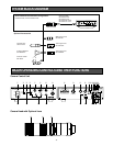
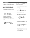
!5 Video Output Connector (VIDEO OUT)
A 1.0 V[p-p] composite video signal is provided at
this connector.
!6 Gen-lock Input Connector (G/L IN)
The colour video signal of the camera is automati-
cally synchronized to the gen-lock signal
(Composite Signal, Black Burst Signal or Video
Sync) when either signal is supplied to this connec-
tor.
Caution: If a camera picture supplied from this
connector, such as a VTR playback picture,
appears jittery on the screen, proper camera
picture synchronization cannot be obtained.
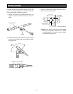
!7 Gen-lock Video 75 Ω Termination On/Off Switch
(75 Ω ON/OFF)
When the gen-lock video signal is looped through
the BNC “T” adopter, set this switch to the OFF
position. If it is not through the BNC “T” adapter, set
this switch to the ON position.
!8 EVR Adjustment Connector
Connect the EVR to this connector.
Normally, keep the connector covered with the rub-
ber cap.
!9 DC 12V Input Terminals (DC 12V IN)
These terminals accept an external DC source sup-
plying nominal power of 12V, 0.7A -1A.
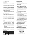
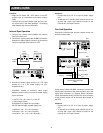
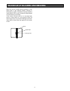
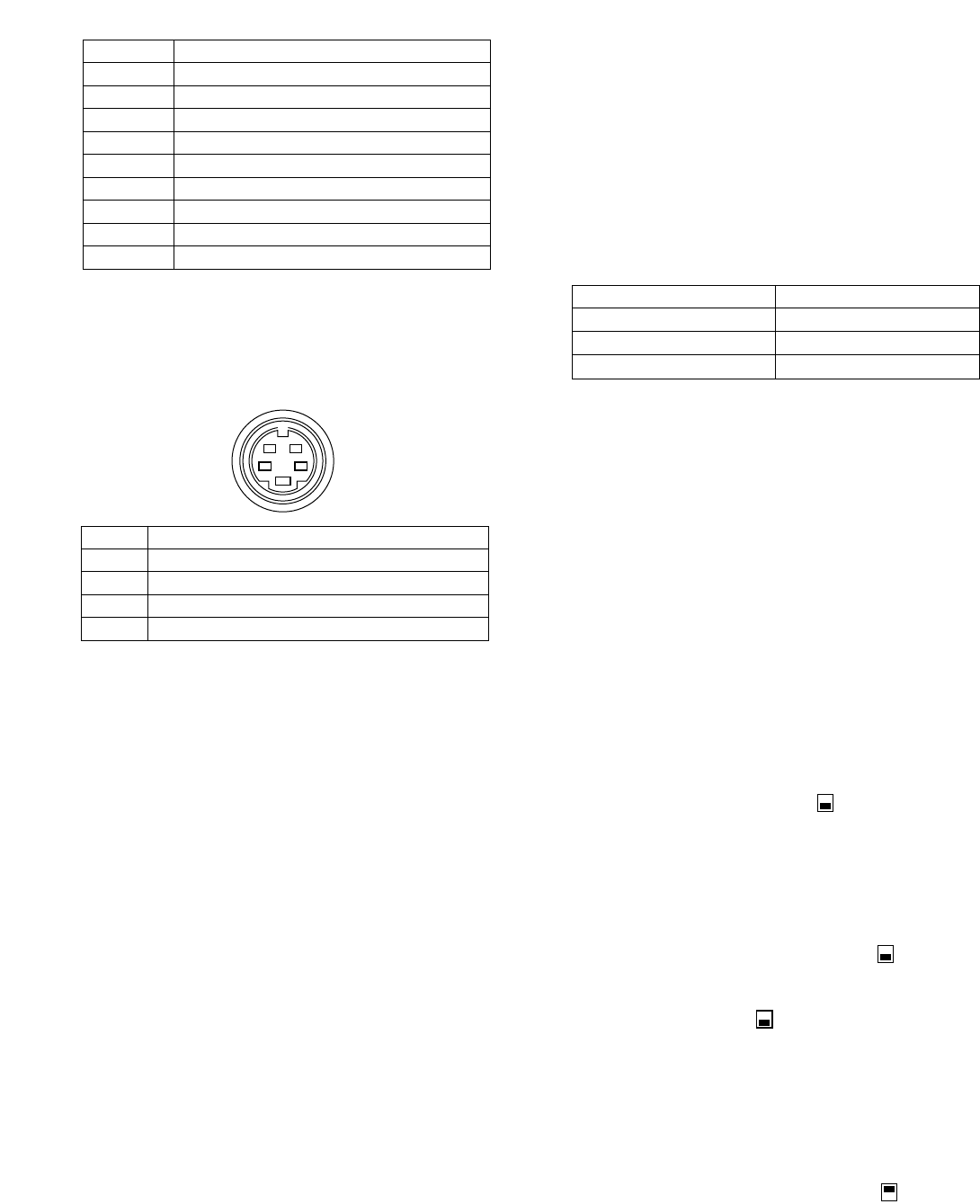
!4 S-Video Output Connector (S-VIDEO OUT)
The luminance (Y) and chroma (C) signals for S-
VHS VTR or monitor are provided at this connector.
Pin Configuration
4
2
3
1
DescriptionPin No.
Y Ground (GND)1
C Ground (GND)2
Y Signal Output: 0.7 V [p-p] (Y level / 75 Ω)3
C Signal Output: 0.3 V [p-p] (burst level / 75 Ω)4
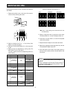
@0 User File Set Indicator
This indicator show the setting steps of the User File
Set as follows:
Setting Indicator
is on process Blinks
is completed Goes off after blinking
is incomplete Lights up
@1 User File Set Switch
This switch is used to change and memorize the
setting of User File Set Function.
@2 User File Item Switch
This switch is used to select a User File Setting item.
Refer to User File Setting on page 10 for selectable
items..
@3 User File Adjust Control
This switch is used to adjust the value of an item
selected with the User File Item switch.
@4 User File Select Switch
This switch selects the setting of SC Coarse (item
No.1) or the sensing zone (item No.7).
@5 User File Set On/Off Switch
This switch is used to activate the User File Setting
Function. When this switch is set to ON, User File
Item switch @2, User File adjust control @3, and User
File select switch @4 are available to set the User
File Settings Function.
@6 This switch is preset at the factory.
Fix this switch to the OFF position.
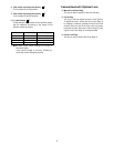
@7 PEAK / AVE Switch
This switch is used to select AGC and ELC detec-
tion levels. Set the switch to ON to select PEAK
detection, or to OFF to select AVERAGE detection.
The video level can be changed using the Video
Level Control !1 on the front panel.
Normally, set this switch to OFF.
@8 White Balance Offset On/Off Switch
By turning on this switch, the white balance offset in
the AWC can be adjusted to a fine level by using the
R/B Gain Controls i.
Normally, keep this switch in the ON position.
on
off
on
off
on
off
on
off
Cautions:
• Connect this to a DC 12 V class 2 power supply
only.
• To prevent fire or electric shock hazard, the UL
listed wire VW-1 style 1007 should be used for
the cable for DC 12V Input Terminal.