15
LSQT0969
Before using
Parts identification and handling
Parts identification and handling
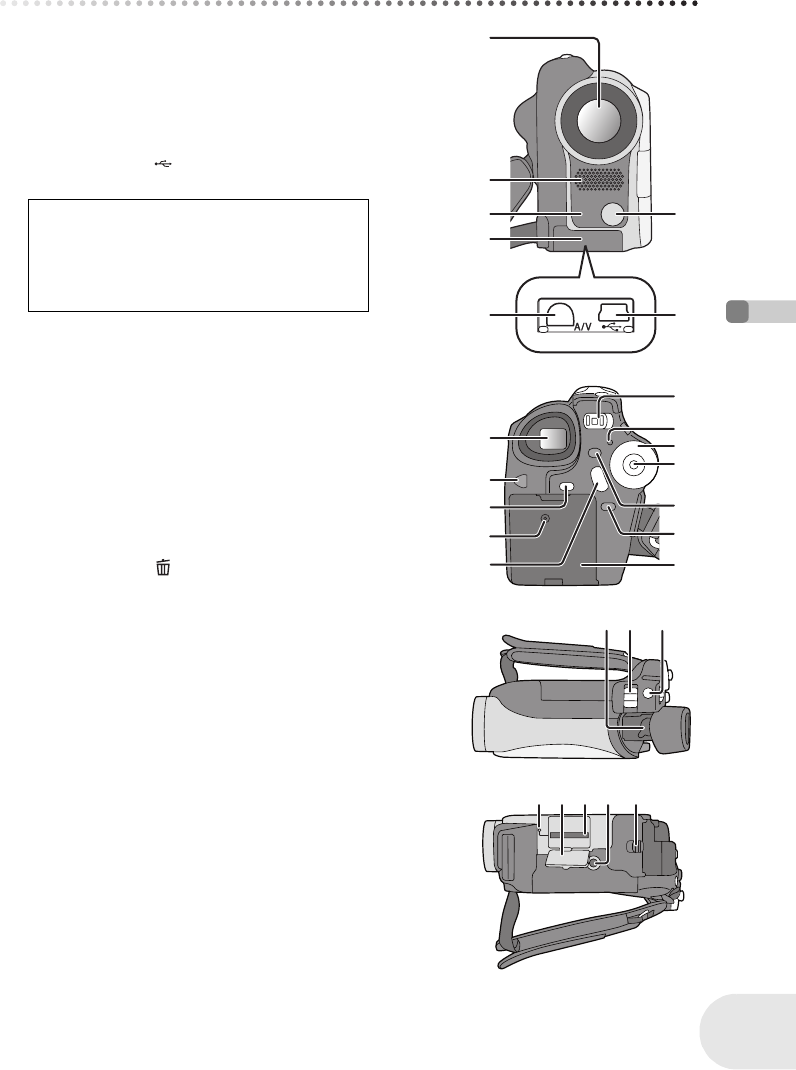
1Lens
2 Microphone (built-in, stereo)
3 White balance sensor (l 59)
4 Terminal cover
5 Audio-video output terminal [A/V] (l 89, 92)
6 Video light (VDR-D200 only) (l 54)
7 USB terminal [ ] (l 93, 106)
8 Viewfinder (l 18, 39)
9 LCD monitor open button [PUSH OPEN] (l 18)
10 Video light button [LIGHT] (VDR-D200 only)
(l 54)
11 DC input terminal [DC/C.C. IN] (l 26)
12 Recording start/stop button (l 41)
13 Power switch [OFF/ON] (l 26)
14 Status indicator (l 26)
15 Mode dial (l 30)
16 Joystick (l 31)
≥ Move up, down, left or right to select items.
≥ Press the center to enter the selection.
17 Delete button [ ] (l 66, 77, 79)
18 Menu button [MENU] (l 36)
19 Battery holder (l 24)
20 Eyepiece corrector knob (l 39)
21 Zoom lever [W/T] (l 45)
Volume lever [sVOLUMEr] (l 62)
22 Photo shot button [PHOTO SHOT]
(VDR-D200 only) (l 43)
23 Card access lamp (VDR-D200 only) (l 29)
24 Card slot cover (VDR-D200 only) (l 29)
25 Card slot (VDR-D200 only) (l 29)
26 Tripod receptacle (l 17)
27 Battery release lever [BATTERY RELEASE] (l 24)
Due to limitations in LCD production
technology, there may be some tiny bright or
dark spots on the viewfinder screen.
However, this is not a malfunction and does
not affect the recorded picture.
1
2
3
4
6
75
8
9
10
12
11
1
3
1
4
1
5
1
6
1
9
1
7
1
8
20 21 22
24 2725 26
23
D200(P_PC)eng.book 15 ページ 2005年11月22日 火曜日 午後3時1分


