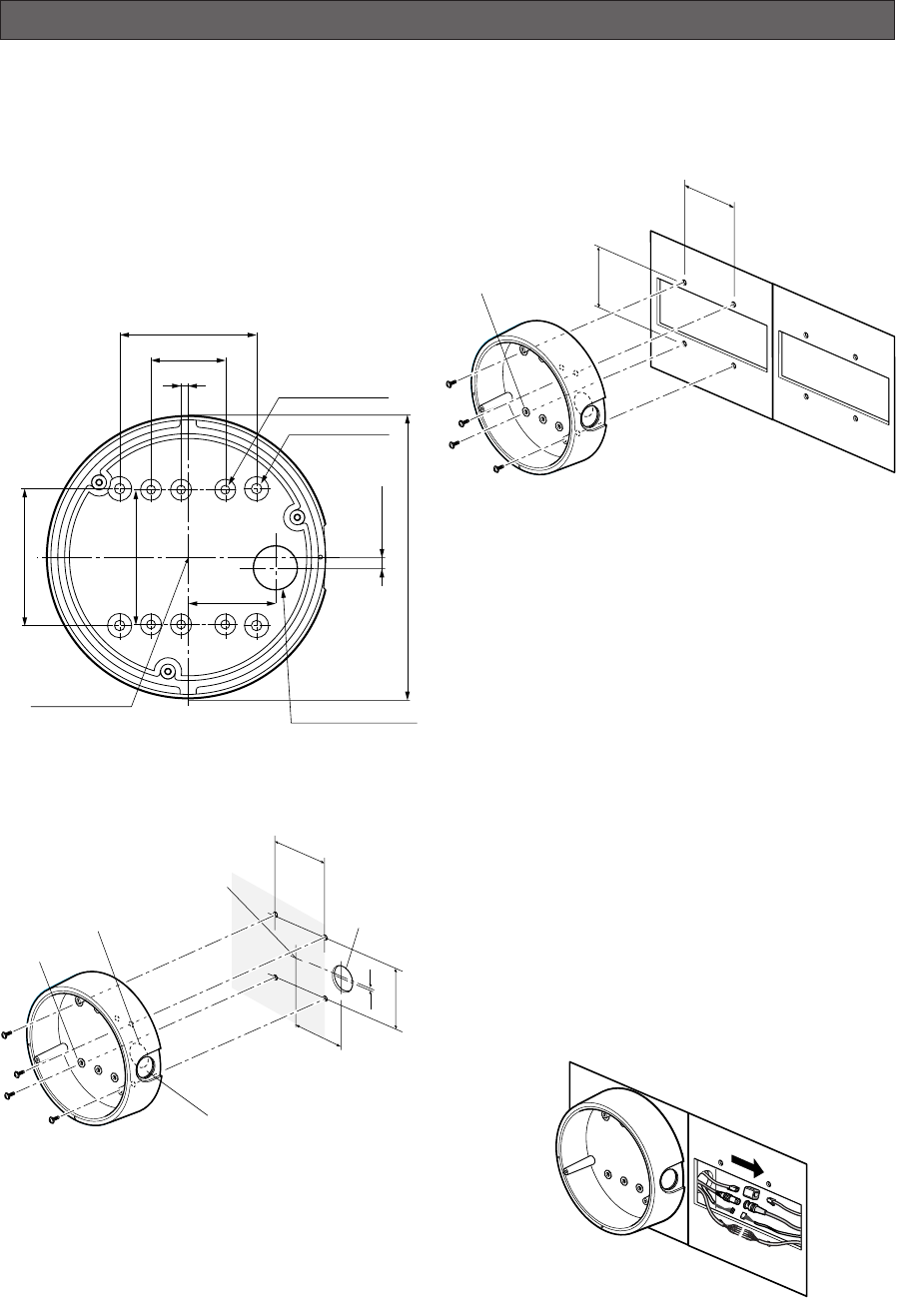
An example of flush mounting is shown. This example
shows two boxes: one is for camera mounting and the
other is for cable junction.
1. Procurement
• Four screws
Locally procure four bracket fixing screws suitable
for the installation surface and structure of the
wall/ceiling or junction box.
• Junction box
When planning to use a junction box(s), procure one
locally that meets the dimensions in the figure.
2. Installation space
Prepare a space on the surface measuring ø175 mm or
more.
3. Cable route
• When routing cables through the wall/ceiling, drill a
hole as shown in the figure.
• When routing cables sideways, open the sideway
cable exit unscrewing the lid with a hexagon
wrench.
-9-
INSTALLATION
■ Installation Plans &
Preparations
The supplied camera-mounting bracket can be
installed directly on the wall/ceiling or on a procured
junction box.
On the bottom of the bracket, there are four 6.5 mm
screw holes and six 5.5 mm holes. Use the appropriate
holes matching to the installation surface.
An example of surface mounting is shown.
83.5 mm
(3-5/16")
46 mm
(1-13/16")
Bracket center
Cable access hole
ø5.5 mm
(7/32")
Sideway cable exit
Bracket fixing screw x4
(Procured locally)
ø27 mm
(1-1/16")
Cable access
hole
7 mm (1/4)
55
(2-3/16")
83.5 mm
(3-5/16")
46 mm
(1-13/16")
ø5.5 mm (7/32")
Bracket fixing screw x4
(Procured locally)
7 (9/32")
φ175 (6-7/8")
Cable Access Hole
φ27 (1-1/16")
4-φ6.5 (6-φ1/4")
6-φ5.5 (6-φ7/32")
55 (2-3/16")
4.4 (3/16")
46 (1-13/16")
85 (3-3/8")
85 (3-3/8")
83.5 (3-5/16")
Bracket Center


