


-11-
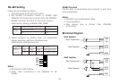
The selected full or half duplex setting will be
enabled after the camera is powered up again.
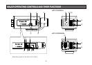
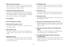
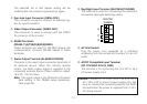
!4 Gen-lock Input Connector (GEN-LOCK)
This connector is used to connect an external sys-
tem for synchronization.
!5 Video Output Connector (VIDEO OUT)
This connector is used to connect with the VIDEO
IN connector of the monitor.
!6 RS485 Terminals
(RS485, T(A)/T(B)/R(A)/R(B)/GND)
These terminals are used for RS-485 Camera site
communication. Connect RS-485 cables to these
terminals.
!7 Alarm Output Terminal (ALARM OUT/GND)
Connects to the alarm input connector (terminal) of
an external device. When the camera detects
motion, the alarm output signal is supplied to the
connected external device (Open collector output:
16 V DC, 100 mA max).
Note: This signal output is not affected by the alarm
data setting in the RS485 setup operations.
(See page 26.)
Caution: Connect to 12 V DC (10.8 V-16 V) or 24 V
AC (19.5 V-28 V) class 2 power supply only. Be
sure to connect the grounding lead to the GND
terminal when the power is supplied from a 24 V
AC power source.
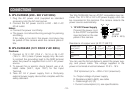
!8 Day/Night Input Terminal (DAY/NIGHT IN/GND)
This terminal is used for connecting the camera to
an external day/night detecting sensor.
!9 AC Inlet Socket
Plug the power cord (supplied as a standard
accessory) into this socket and connect it to an AC
outlet.
@0 AC/DC Compatible Input Terminal
(DC 12V IN/AC 24V IN, GND)
This terminal is for connecting the 12 V DC or 24 V
AC power supply cord.
B1
2
3
!6
!7
!8
4
5
6
7
8
9
T
IN/OUTPUT
TERMINAL
A
B
R
A
GND
RS485
ALARM
DAY/
NIGHT
GND
OUT
GND
IN