


11 12
TM Glows red to indicate that the Model 2112 has
been placed in Test Mode. The unit can be placed in
test mode by the local or remote user.
NS Glow red to indicate that the local Model 2112 has
not yet connected with the remote.
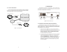
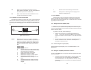
4.3 ETHERNET LED STATUS MONITORS
The Model 2112 features two LEDs that monitor general operating
status and the 10Base-T twisted pair link integrity (located on the rear
of the unit). Figure 5 (below) shows the LEDs located directly beneath
the RJ-45 jack. Following Figure 5 is a description of each LEDs func-
tion.
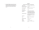
Status Blinks yellow from one to four times to indicate
system status. Each pulse pattern is separated by a
2 second “off” period. Greater pulse patterns have
higher priority (buffer saturation has greater priority
than an empty MAC table). Valid system statuses
are:
Pulses
Status
1 System status ok.
2 No MAC entries in the MAC address table.
3 Clear to send (CTS) or Carrier Detect (CD)
from base unit is not asserted.
4 Bridge module buffer is saturated.
5 WAN receive frame(s) too large.
6 WAN receive frame(s) not octet aligned.
7 WAN receive frames(s) aborted.
8 Detected WAN receive frame(s) with bad
CRC.
9 Detected LAN receive frame(s) too large.
10 Detected LAN receive frame(s) not octet
aligned.
11 Detected LAN receive frame(s) with bad CRC.
Link Glows green to indicate good link integrity on the
10Base-T twisted pair line.
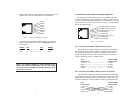
4.4 TEST MODES
The Model 2112 offers a proprietary loopback test mode, plus a
built-in V.52 BER test pattern generator, to evaluate the condition of
the modems and the communication link. These tests can be activated
physically from the front panel.
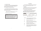
4.4.1 Using Local Line Loopback (LLB)
The Local Line Loopback (LLB) test checks the operation of the
local Model 2112, and is performed separately on each unit. Any data
sent to the local Model 2112 in this test mode will be echoed (returned)
back to the user device.
To perform a LLB test, follow these steps:
1. Activate LLB. Move the front panel toggle switch UP to
“Local”. Once LLB is activated, the Model 2112 transmitter
output is connected to its own receiver. The “TM” LED should
be lit.
2. Verify that the data terminal equipment is operating properly
and can be used for a test. If a fault is indicated, call a
technician or replace the unit.
4.4.2 Remote Digital Loopback (RDL)
Remote Digital Loopback (RDL) is not an available feature on the
Model 2112.
4.4.3 Using the V.52 (BER) Test Pattern Generator
To use the V.52 BER tests in conjunction with the loopback test follow
these instructions:
1. Locate the “511/511E” toggle switch on the front panel of the
2112 and move it UP. This activates the V.52 BER test
mode and transmits a “511” test pattern into the loop. If any
errors are present, the local modem’s red “ER” LED will blink
sporadically.
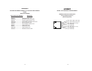
Quik-Connect
Interface Module
Interface Port
Figure 5. Model IM1/I Panel
Status LED
Link LED