


13 14
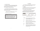
2. If the above test indicates no errors are present, move the
V.52 toggle switch DOWN, activating the “511/E” test with
errors present. If the test is working properly, the local
modem's red “ER” LED will glow. A successful “511/E” test
will confirm that the link is in place, and that the Model
2112’s built-in “511” generator and detector are working
properly.
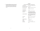
APPENDIX A
PATTON ELECTRONICS MODEL 2112 SPECIFICATIONS
LAN Connection: RJ-45, 10Base-T, IEEE 802.3 Ethernet
MAC Address Table Size: 4096 entries
MAC Address Aging: MAC addresses deleted after 8 minutes
inactivity
On-board Memory: 512 KB RAM; 128 KB FLASH
Frame Latency: 1 frame
Transmission Line: Two-Wire unconditioned twisted pair
Diagnostics: V.52 compliant bit error rate pattern
(511/511E pattern) generator and detec
tor with error injection mode; Local Line
Loopback activated by front panel switch
LED Status Indicators: TD, RD, CTS, CD, DTR, NS(no signal),
ER (error), TM (test mode) on front
panel; (1) general status; (1) link integri
ty on rear panel
Connectors: RJ-45 on line side; RJ-45 on Ethernet
Port
Power: 100-253 VAC, 50-60 Hz (universal
input);
Temperature Range: 32-122°F (0° -50°C)
Altitude: 0-15,000 feet
Humidity: 5 to 95% non-condensing
Dimensions:
7.3” x 6.6” x 1.62” (185mm x 168mm x
41mm)