


7 8
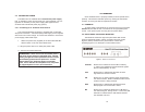
3. Observe the Signal/Pin relationships on the Model 2112’s Line
Interface jack. This Line Interface is a 2 wire interface.
4. Connect the Line interface of a Model 2112-CO to the Line
interface of a Model 2112-CP with a twisted pair cable as
shown below:
SIGNAL
PIN PIN SIGNAL
Tip 4 --------------------------4 Tip
Ring 5 --------------------------5 Ring
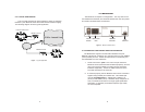
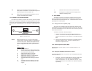
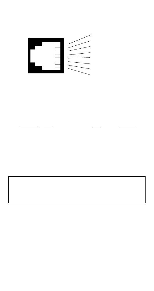
3.2 CONNECTING THE 10BASET ETHERNET INTERFACE
The RJ-45 jack labeled “Interface Port” is the 10BaseT interface.
This port is designed to connect directly to a 10BaseT network. Figure
4, below, shows the Signal/Pin relationships on this interface. You may
connect this port to another Ethernet port via a Type 4 or Type 5 cable
that is up to 330 feet long.
3.2.1 Connecting the 10Base-T Ethernet Port to a Hub
The Model 2112 10Base-T interface is configured as DTE (Data
Terminal Equipment), just like a 10Base-T network interface card in a
PC. Therefore, it “expects” to connect to a 10Base-T Hub using a
straight-through RJ-45 cable. Use the diagram below to construct a
cable to connect the 2112 to a 10Base-T Hub.
2112 10Base-T Hub
RJ-45 Pin No. RJ-45 Pin No.
1 (TX+) -------------------------------------------------1 (RX+)
2 (TX-)--------------------------------------------------2 (RX-)
3 (RX+)-------------------------------------------------3 (TX+)
6 (RX-)--------------------------------------------------6 (TX-)
3.2.2 Connecting the 10Base-T Ethernet Port to a PC (DTE)
The Model 21121 10Base-T interface is configured as DTE (Data
Terminal Equipment). If you wish to connect the 2112 to another DTE
device such as a 10Base-T network interface card in a PC, you must
construct a 10Base-T crossover cable as shown in the diagram below.
2112 10Base-T DTE
RJ-45 Pin No. RJ-45 Pin No.
1 (TX+) 1 (TX+)
2 (TX-) 2 (TX-)
3 (RX+) 3 (RX+)
6 (RX-) 6 (RX-)
Figure 4. Line Interface.
1 TD+ (data output from 2112
2 TD- (data output from 2112)
3 RD+ (data input to 2112)
4 (no connection)
5 (no connection)
6 RD- (data input to 2112)
7 (no connection)
8 (no connection)
1
2
3
4
5
6
7
8
NOTE: Any modular twisted pair cable connected to the
Model 2112 must be shielded cable, and the outer shield
must be properly terminated to a shielded modular plug on
both ends of the cable
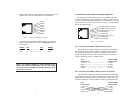
Figure 3. Model 2112 twisted pair line interface.
1 (N/C)
2 (N/C)
3 (N/C)
4 (Tip)
5 (Ring)
6 (N/C)
7 (N/C)
8 (N/C)
1
2
3
4
5
6
7
8