


5 6
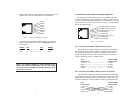
2.3 TYPICAL APPLICATION
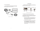
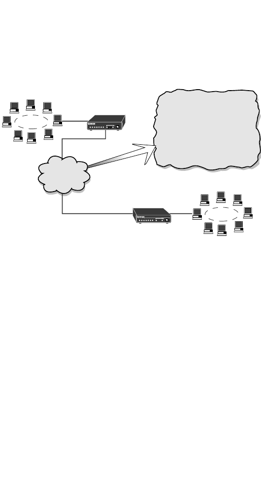
The 2112-CO and 2112-CP work together to create an extension
between 2 peer Ethernet LANs with all the benefits of MAC bridging.
The following diagram shows a typical application
3.0 INSTALLATION
The Model 2112 requires no configuration. You only need to con-
nect the Ethernet interface, line interface between the units and power.
This section describes these connections.
3.1 CONNECTING THE TWISTED PAIR LINE INTERFACE
The Model 2112 supports communication between two peer
Ethernet LAN sites at a distance up to 3.6 miles (5.8 km) over 24AWG
(.5mm) twisted pair wire. Follow the steps below to successfully con-
nect the Model 2112 Line Interfaces.
1. These units work in
pairs
. One unit in the pair must be a
Model 2112-CO (looks like Central Office equipment), and the
other unit must be a Model 2112-CP (looks like Customer
Premises equipment). It does not matter which end is the
2112-CO and which is the 2112-CP.
2. To function properly, the two Model 2112s must be connected
together using twisted pair metallic wire. This twisted pair
must be
unconditioned
, dry, metallic wire, between 19
(.9mm) and 26 AWG (.4mm). Standard dial-up telephone cir-
cuits, or leased circuits that run through signal equalization
equipment, or standard, flat modular telephone type cable,
are
not acceptable
.
Corporate Headquarters
LAN
LAN
Ρεμοτε/Σατελλιτε Οφφιχε
Model 2112-CO
Model 2112-CP
2-Wire Leased Line
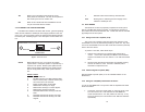
Figure 2. Model 2112 Rear Panel.
Figure 1. Typical Application
Line
Interface
10BaseT
Interface
IEC Power
Jack
Power
Switch