11
3.3 CONNECTING THE LINE PORT
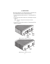
Follow the steps below to connect the CopperLink-T line port:
1. Obtain a single-twisted pair cable with an RJ-45 plug connector at
each end.
2. Plug one end of the cable into the RJ-45 socket (labeled Line) on the
CopperLink-T .
3. When the remote and local extender units synchronize, the front-
panel Link LED will turn on.
3.4 CONNECTING THE CIRCUIT INTERFACE
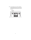
Your CopperLink-T comes with either an RJ-48C or an RJ-48C and dual
BNC for connection to a T1 or E1:
• Model 2113 - E1: 120-Ohm RJ-48C and dual 75-Ohm BNC connec-
tors
• Model 2115 - T1: RJ-48C
To connect the twisted pair cable to the CopperLink-T T1/E1 port:
1. Attach the male connector of the twisted pair cable to the female RJ-
48 connector on the CopperLink-T.
2. Attach the other end of the cable to the RJ-48 connector on the local
T1 or E1.
Note
When attaching the 2113/2115 directly to a T1/E1 circuit,
a straight through twisted pair cable can be used. When
attaching the 2113/R or 2115/R to a device, please use
the enclosed T1/E1 cross over cable for proper operation.
The interconnecting cables shall be acceptable for
external use and shall be rated for the proper applica-
tion with respect to voltage, current, anticipated tem-
perature, flammability, and mechanical serviceability.
CAUTION


