


10 Pelco Manual C1917M (12/97)
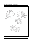
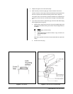
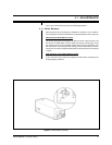
9. Connect a video cable to the VIDEO OUT connector on the camera (refer to
Figure 8). Refer to Table B for the type of video coaxial cable to use.
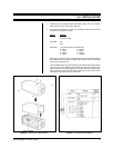
10. Set the SYNC (synchronization) switch.
INT (internal): for using the internal synchronizing signal.
L.L. (line lock): for locking the camera operation to the supply power frequency
as a synchronizing signal. The vertical drive frequency of the camera is locked
to the AC power frequency (60 Hz) instead of the internal clock of the camera
(59.94 Hz), avoiding picture roll during camera switching operations.
Proceed to Section 4.1, ADJUSTMENTS.
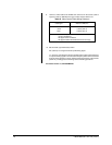
Table B. Video Coaxial Cable Wiring Distances
Cable Type* Maximum Distance
RG59 750 ft (229 m)
RG 6 1,000 ft (305 m)
RG11 1,500 ft (457 m)
* Minimum cable requirements:
75 ohms impedance
All-copper center conductor
All-copper braided shield with 95% braid coverage