Pelco Manual C540M (6/98) 23
5.2 VCR CONTROL
VCRs can be connected and controlled via a CM9760 system and CM9760 key-
board in the following configurations:
1. Via a start/stop signal from the Pelco Alarm Interface Unit (no full control)
2. Via a Relay Interface unit, enabling remote control using the CM9760 key-
board
3. Via a Pelco Infra-Red Control System, enabling remote control using the
CM9760 keyboard
VCRs can be controlled from the CM9760 keyboard if
1. The VCRs have been modified appropriately. For instance, it might be neces-
sary to add hardware that provides alarm signal feedback.
2. Appropriate Pelco interface equipment is included.
3. VCR video outputs are connected as inputs to the Pelco CM9760 System.
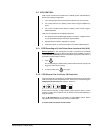
5.2.1 VCR Recording with the Pelco Alarm Interface Unit (AIU)
Manual operation:
in this configuration the VCR is connected from a CM9760
output in series to a video monitor. With an appropriate Pelco installation, and where
a
user-definable control key
has been allocated the appropriate VCR function, it
is possible to record footage as follows:
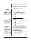
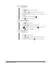
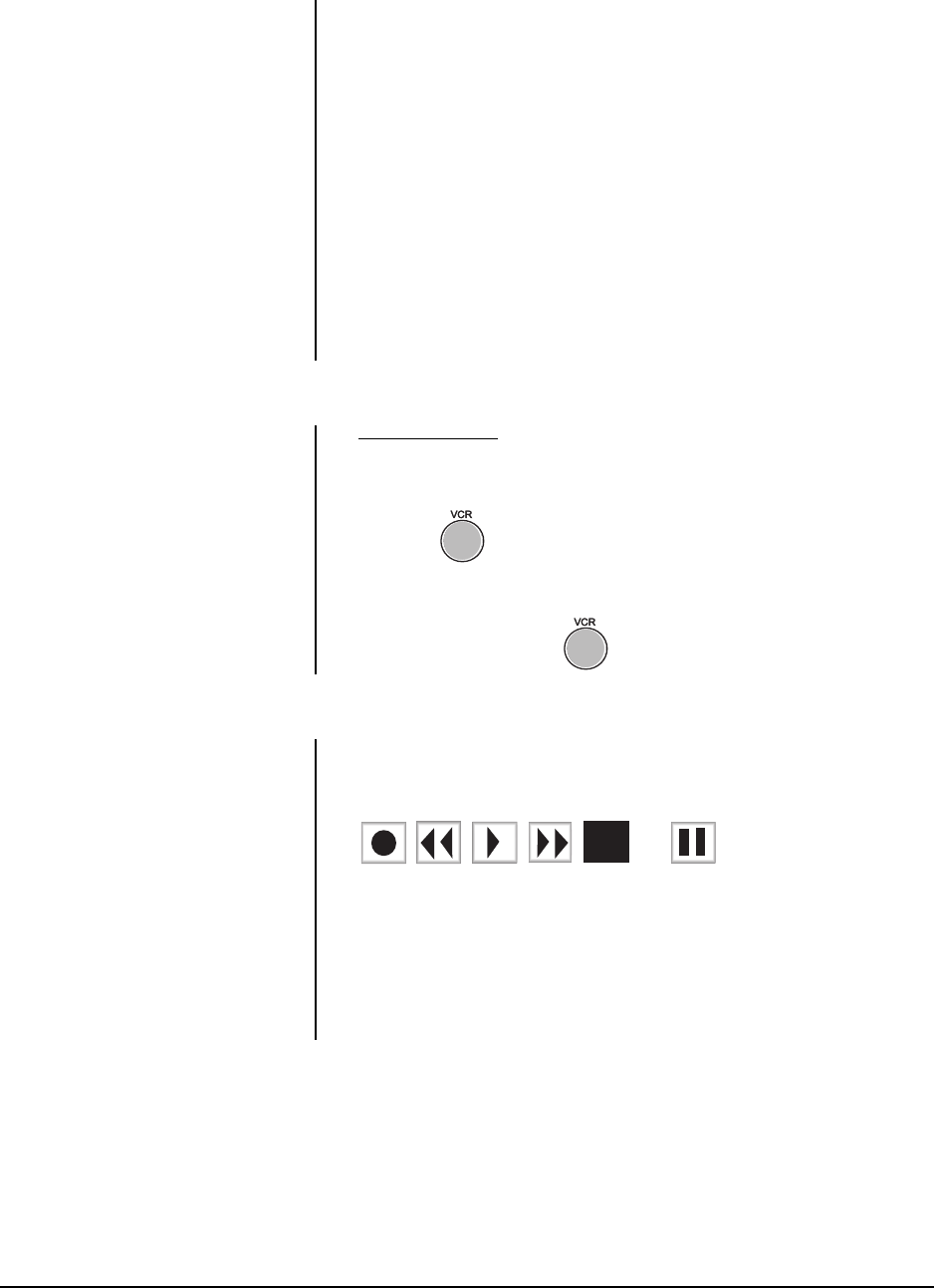
1. Press .
The corresponding key will illuminate, while the Alarm Interface Unit (AIU) will
trigger the VCR to start recording.
2. To stop the VCR, press once again.
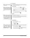
5.2.2 VCR Control Via the Pelco IR Controller
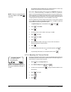
In Pelco IR-based CCTV installations, the CM9760 keyboard can be used to select
VCRs and to operate their standard functions. VCRs may be controlled using the
multipurpose function keys
that select the
VCR
icons:
, , , , , and .
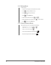
Via the Pelco IR controller, a single general purpose interface (GPI) is used to
control four VCRs, and a maximum of up to 32 GPIs can be accommodated by a
single IR controller.
Up to 16
IR Controllers
can be connected to a single CM9760 system. Sixteen
fully populated IR Controllers provide control over 2048 VCRs.
To control VCRs, see Section 5.3 GPI control.


